PuceBaboon
The "files" section (below) has a downloadable link for the example .ino file. The code is very simple and implementing it in plain C using the standard, or open, SDK shouldn't present any problems.
The are basically only three, very short, routines.
- LatchOn()
- LatchOff()
- ChkAutoOff()
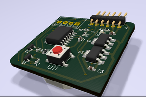
The names pretty much tell you all there is to know. When your ESP first receives power, the very first thing you call, even (especially!) before initiating the serial connection, is LatchOn(). This simply takes the designated GPIO pin high, switching on the 2N7000, which in turn switches on the AO3415, so when the user removes their finger from the "on" switch (a momentary contact push switch), the power is held on by the ESP8266 itself. The debug message is pretty much a waste of time, as the serial port isn't initialized yet. :-)
LatchOff() is called when your ESP8266 has finished whatever task it was assigned to do, or when the RUNT_MAX (runtime max) time limit is reached. I have mine set to three minutes with:-
#define RUNT_MAX 3 * 60 * 1000The ChkAutoOff() routine is the one which takes care of that auto-off timeout and should be called each time through your main loop.
It would be relatively simple to implement a "busy" flag so that the runtime counter is reset to zero (inhibiting the auto-off function) if the ESP8266 is still actively running some critical task. In my case (a doorbell application), the ESP is pretty much done once it has passed off the bell-push information to the MQTT server, so it just sits there displaying a mini "mood light" LED colour fader until it hits RUNT_MAX.
 Taiwo
Taiwo
 Capt. Flatus O'Flaherty ☠
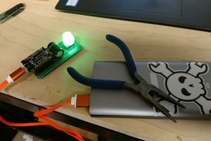
 scott.mcgimpsey