 biemster
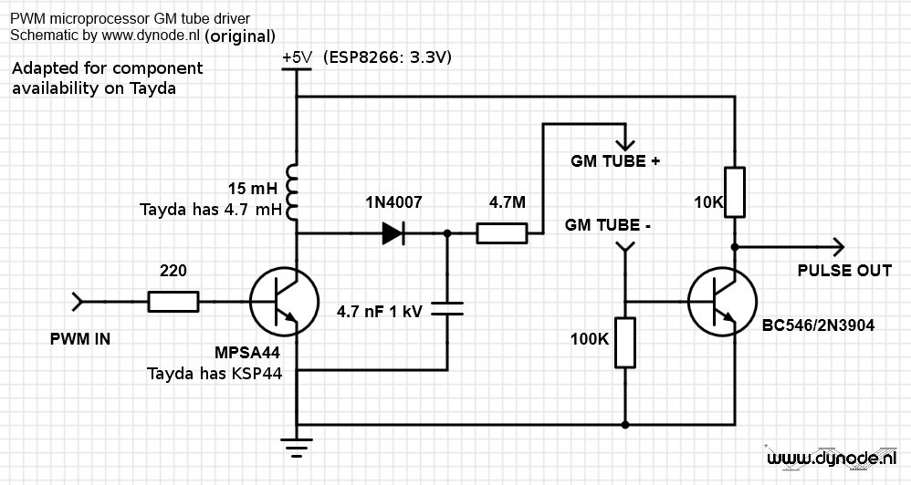 This circuit requires a PWM frequency of about 10kHz or higher, for the HV output not to have a large ripple (See the LTspice simulation in FILES section). A patch for MicroPython (see logs) addresses this issue.
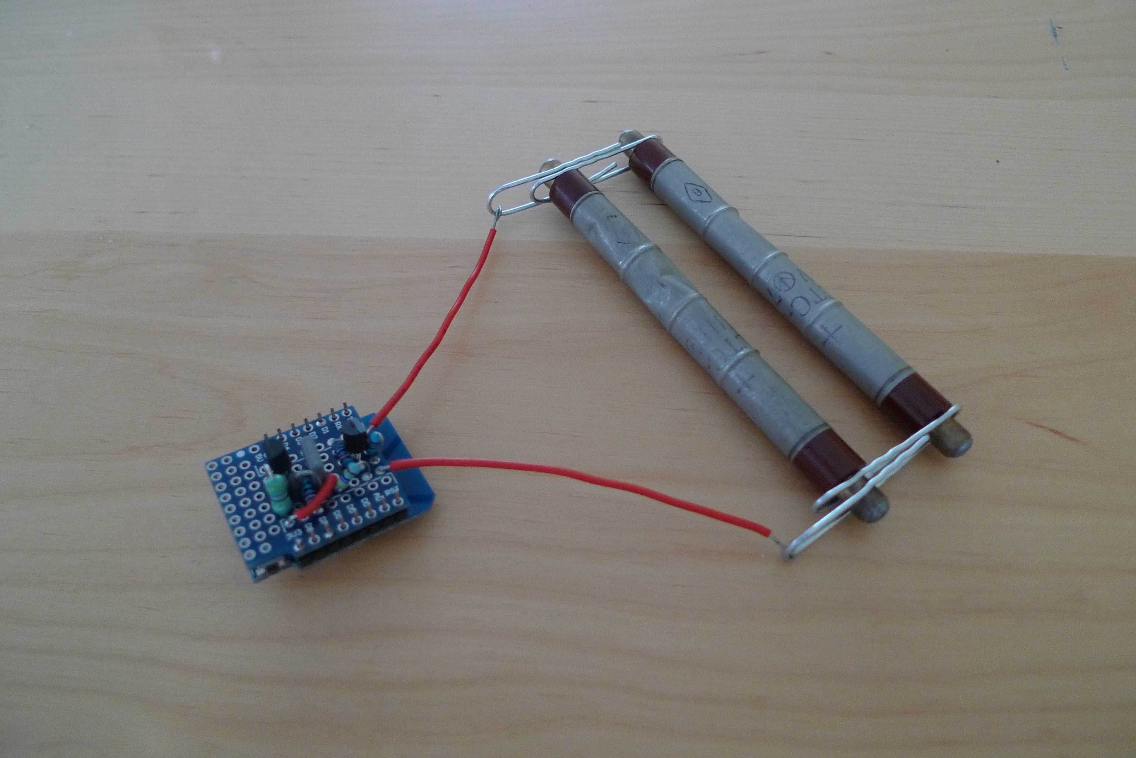
I've adapted the parts for this project given on https://www.dynode.nl/trinket-powered-geiger-counter/ according to availability on Tayda, because I'm trying to keep the total cost of the project around 15 euro. The Geiger tube is the most expensive part, but can be found from Ukraine for under 10 dollar.
I use a WeMos D1 mini for easy programming of the ESP8266.
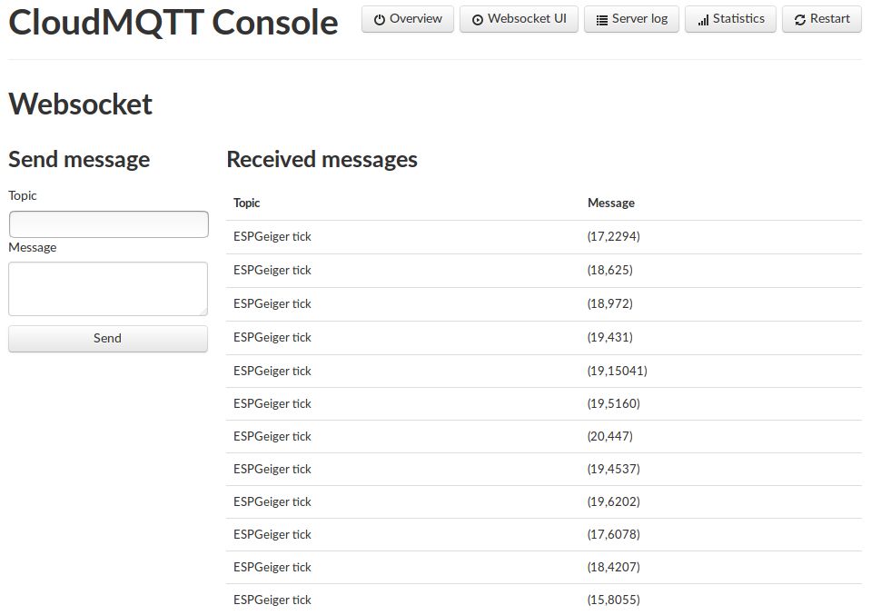
Code will live in https://github.com/biemster/ESPGeiger. It will be a library that will handle the low level stuff such as PWM and pin assignments, and a general part that will communicate the measurements out to the world.
Since it looks like the PWM duty needs to be calibrated to get the right HV on the tube, the library will have a calibrate function that tries to produce the following plot:
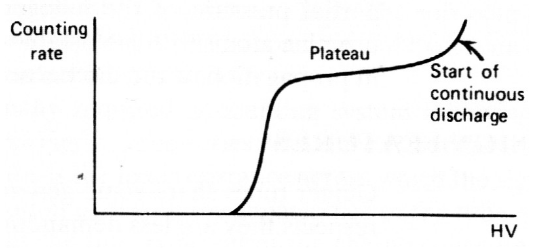 The plateau region is the desired operational region for a Geiger tube. In my case the plot will be the Counting rate as a function of the PWM duty parameter, and not HV as in the example above.
Using this calibration method to determine the duty of the PWM will eliminate the need of special HV testing equipment, since a general multimeter is not able to measure the HV due to the very low current in the circuit (I tried and failed. I could use a gigohm resistor to make a 1000x probe, but I don't have those at the moment. Also, this calibration adds a bit of extra physics to the whole project).


 Lixie Labs
 Louis H
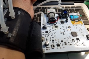
 GCY
GCY
 muzi
muzi
ok thank you.