 Dan Royer
Robot Overlord 3 makes it easy for your to simulate and program robots. It's great for robot arms, dogs, crabs, and more. Join us! Help make robots easier for everyone.
0%
0%
Robot Overlord 3
3D simulation and control software for robots
Become a Hackaday.io member
Already have an account? Log in.
Just one more thing
To make the experience fit your profile, pick a username and tell us what interests you.
Pick an awesome username
hackaday.io/
Your profile's URL: hackaday.io/username. Max 25 alphanumeric characters.
Pick a few interests
Projects that share your interests
People that share your interests
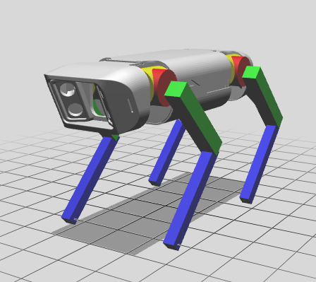
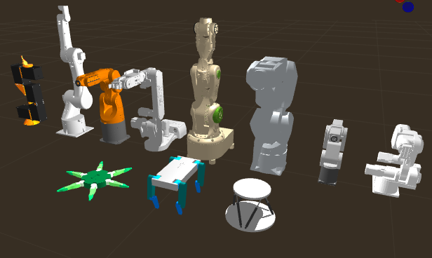 (back: Sixi3, Ben, K1, AR4, Mantis, Arctos, Meca500, PAROL6. front: crab, dog, and stewart examples)
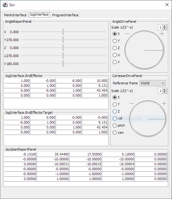
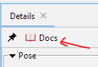 Straight to the API documentation. Nice!


 Ted Huntington
 theotherlonestar
 Hippolyte
Hi,Great project. I'm very interested in the design process of this robotic arm.Now,I‘m a college student, and I want to design a 3D printing mechanical arm like this by myself, but I don't know how to start,I would appreciate it if you could give me some hints.