NOTE: REDESIGN IN PROGRESS SO THIS WILL BE COMPATIBLE WITH THE PI ZERO W. CHECK BACK LATER.
First, I want to give well-earned credit to this wonderful project. (Read through it, it's very informative.) I'm truly standing on the shoulders of giants here: all I've done is make it as small as possible, leveraging my technique of using resistors to attach a circuit board to the Pi Zero like I did here. I guess it's kind of a reductionist thing. The result is a somewhat slow WiFi adapter for the Pi Zero for under $5.
Here's the schematic. The connection from test point P1-EN to the ESP module EN pin isn't shown. Also not shown are 33 ohm series resistors between P2 and the Pi Zero, on all but P2-17, 30, and 34, which are directly connected. Pretty simple isn't it?

DOING THE WORK
I spent an afternoon designing the board, and sent it off to OSH Park. I was somewhat anxious: I'd never done a cutout before, and the cutout had to be made oversize since it had rounded edges. I also had to make a footprint for the ESP, so I didn't know if it was accurate. I didn't know if my power and ground traces were large enough. I was worried about cross-talk in the data lines since there wasn't enought room for a ground plane. And I'd never lap-soldered a module before: could I make the necessary low-resistance connections by hand? So many worries.
As for software, the original kernel module source only needed some small changes. I changed the reset GPIO since I didn't want to fiddle with module parameters. I added a few lines of code to both the source and the overlay so the overlay would auto-load the module. I changed a couple of makefiles so the module would compile in-tree. After a quick compile, I had a shiny new kernel module!
IT'S SO SIMPLE IT CAN'T FAIL, RIGHT?
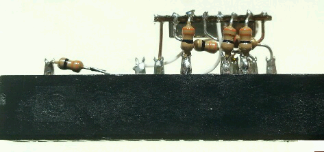
While I was waiting for my boards, I built a prototype by soldering short resistors from the ESP to a salvaged IDE connector like this:
I triple checked everything, installed the config files, booted up, and loaded the kernel module. Woo, no smoke! But it didn't actually work. Kernel messages stated that the ESP wasn't resetting. After looking at the source code, it became apparent that it was assumed that the reset line had a pull-up. To do a reset, the code simply set the GPIO as an output with value 0, waited a bit, then freed the GPIO, relying on the pull-up to bring the pin to a logic 1. Of course the GPIO I had selected for reset had a default pull-down. I fixed this by changing the overlay to enable a pull-up on the reset GPIO, compiled the overlay and rebooted.
It was still dead as a doornail. (What is a doornail, anyway?) It was time for the mighty oscilloscope, so I hauled it out and connected it up. I checked the SDIO clock: it seemed to be working. While probing the SDIO data lines, one of the resistors came loose from the ESP because of the probe strain. Then I noticed that one of the other resistors had also come loose: I had cold solder joints! This hadn't happened to me for a long time, so I wasn't expecting it. It was probably caused by the pads on the end of the ESP being so small: they're only designed for lap soldering, not wires. I re-soldered the end connections with plenty of flux and solder, and re-booted.
And it worked! The kernel module loaded, and I could do an iwlist scan. It even picked up my settings from the previously installed USB WiFi dongle, and connected to my access point.
When I received the circuit boards I de-soldered the module from the connector and soldered it to the circuit board. It fit extremely well: the cutout and footprint were perfect. On power-up everything worked flawlessly. I had worried for naught!
Here's what it looked like. The assembly is barely bigger than the Zero:

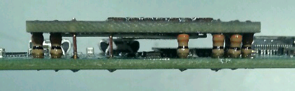
This edge view shows how thin the assembly is:
BENCHMARKING
It was time for a speed test! I compiled the netio tool, set up a server, and did a test. I was getting better than 3 megabits per second. I tested a USB dongle in another Pi, at the same location, and I got just over 10...
Read more »


 Thorsten Jaeger
 Mirko
Mirko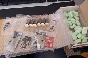
 Jon Davies "Woody"
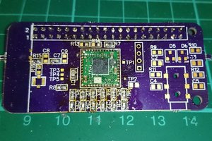
 jacksonliam
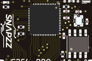
Heyy so I put your boards on panels I was ordering from DirtyPCBs, and this is what I got now:
I think I have about 10, will keep 5 to myself, but to others who like this project - will ship those to Europe/Russia for the (likely, very low) price of sending a flat envelope, since I have so many I'm unlikely to actually use them all in my lifetime =)