Modern sail boat transducer and chartplotter systems offer advanced features which show optimal tacks and laylines to allow the most efficient and fast routing to the destination to be easily determined. My project aimed to recreate this functionality without the many thousands of pounds required for a chartplotter with this functionality and the new compatible instrument transducers to feed it with the boat performance information.
Recent plugin developments in the open source PC based navigation software OpenCPN, meant that this functionality was now within reach, my challenge was to get the data from a variety of legacy transducers into the PC system to allow the calculations to take place.
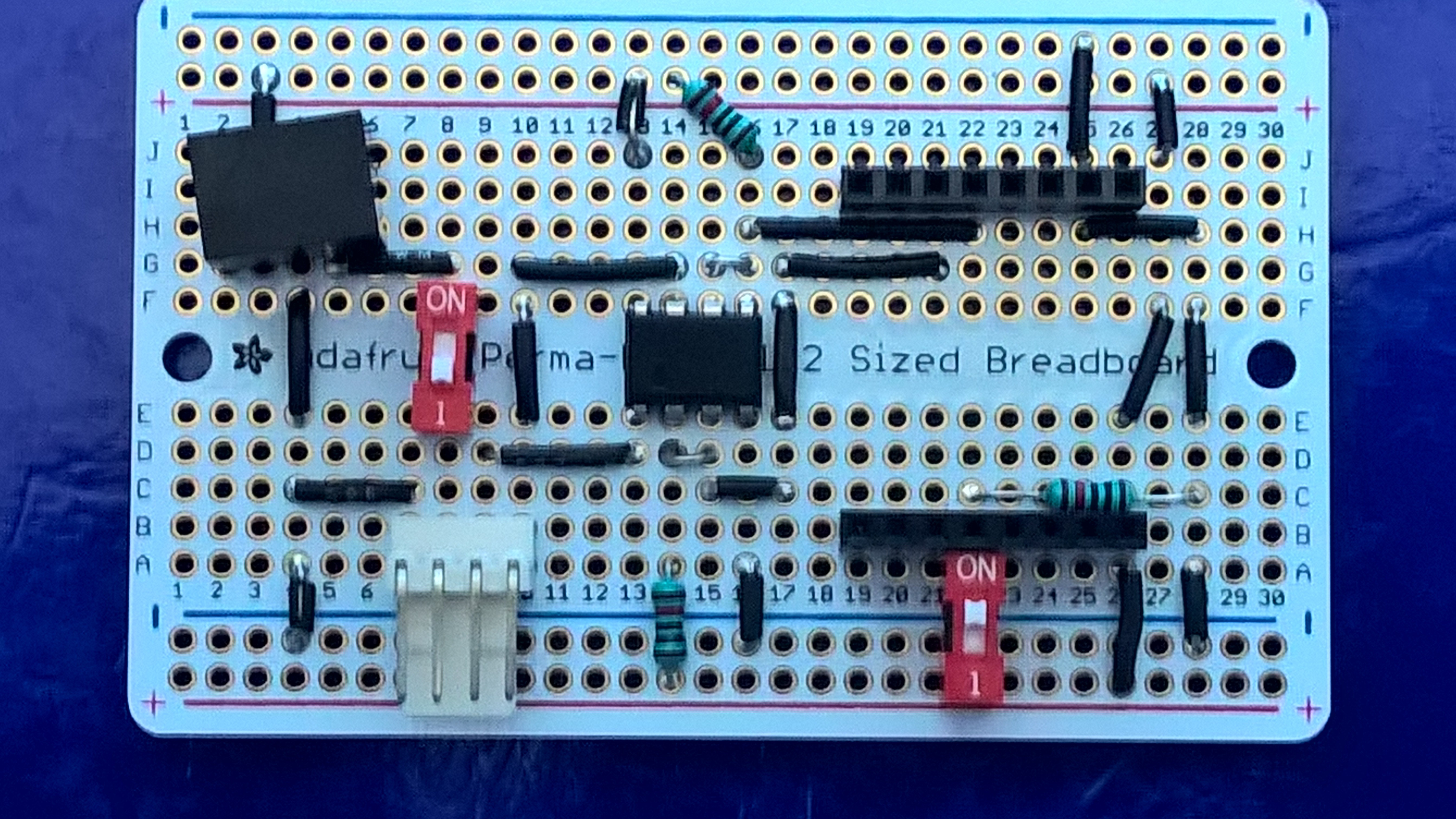
My old wind transducer unit was not designed to be networked and therefore did not have a NMEA output stream. This project aims to overcome this limitation by capturing the I2C signal from the NASA MArine wind transducer which is intended to run a display repeater unit and then decode this signal and upload it to a WifI NMEA hub. Thus allowing this data to be shared with my Tablet.
 ACROBOTIC Industries
 Emach00
 vcazan
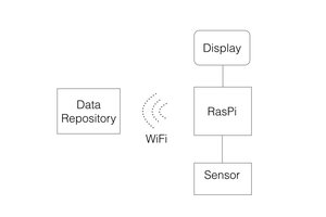
 Nocternal
I'm looking into doing the same same thing on an arduino board, and I was wondering if there is any information about the scale used (MPH/Knots/ meters per sec) in the IC stream?
If one would change the scale the value displayed would change and hence the IC stream, so what unit do you put in the 'MWV'-sentence?