 James
JamesThe RetroRiter needs a case. Or at a minimum some bits to keep it in a roughly ridged shape and keep the exposed PCBs protected.
When I had originally picked up the PiZero, I also got a case from C4Labs.net (the Zebra Zero... which seems discontinued but similar to the Nucleus Zero) along with a header (which I may regret as it adds bulk but makes prototyping easier... I might buy a second Pi Zero to use on the final product). The case looks nice, and there is something pleasing about the juxtaposition of a wood case for a PCB covered in solder and SMD components. I liked the screws that came with the Zebra Zero case, but couldn't figure out the size. Luckily C4 Labs responded to my cry for help on the twitter (size 4-40):
@10thMarshall they are 4-40 size stainless steel screws.
— C4 Labs (@theC4Labs) August">https://twitter.com/theC4Labs/status/760953386732707840">August 3, 2016
So the Pi Zero is protected and can be secured. The next part of concern is the HDMI display. For this, I decided to order a bunch of hex standoffs from Amazon to play around with. They are great to prototype with, look cool in bronze, and give a lot of flexibility in sizing. My initial plan was to make the computer as a sandwich: plywood baseplate and display as the bread, with the Pi Zero and whatever else as the meat. The standoffs would secure the display to the base, and let me play around with the spacing. Here's a shot of the display with M3 (I think) standoffs:
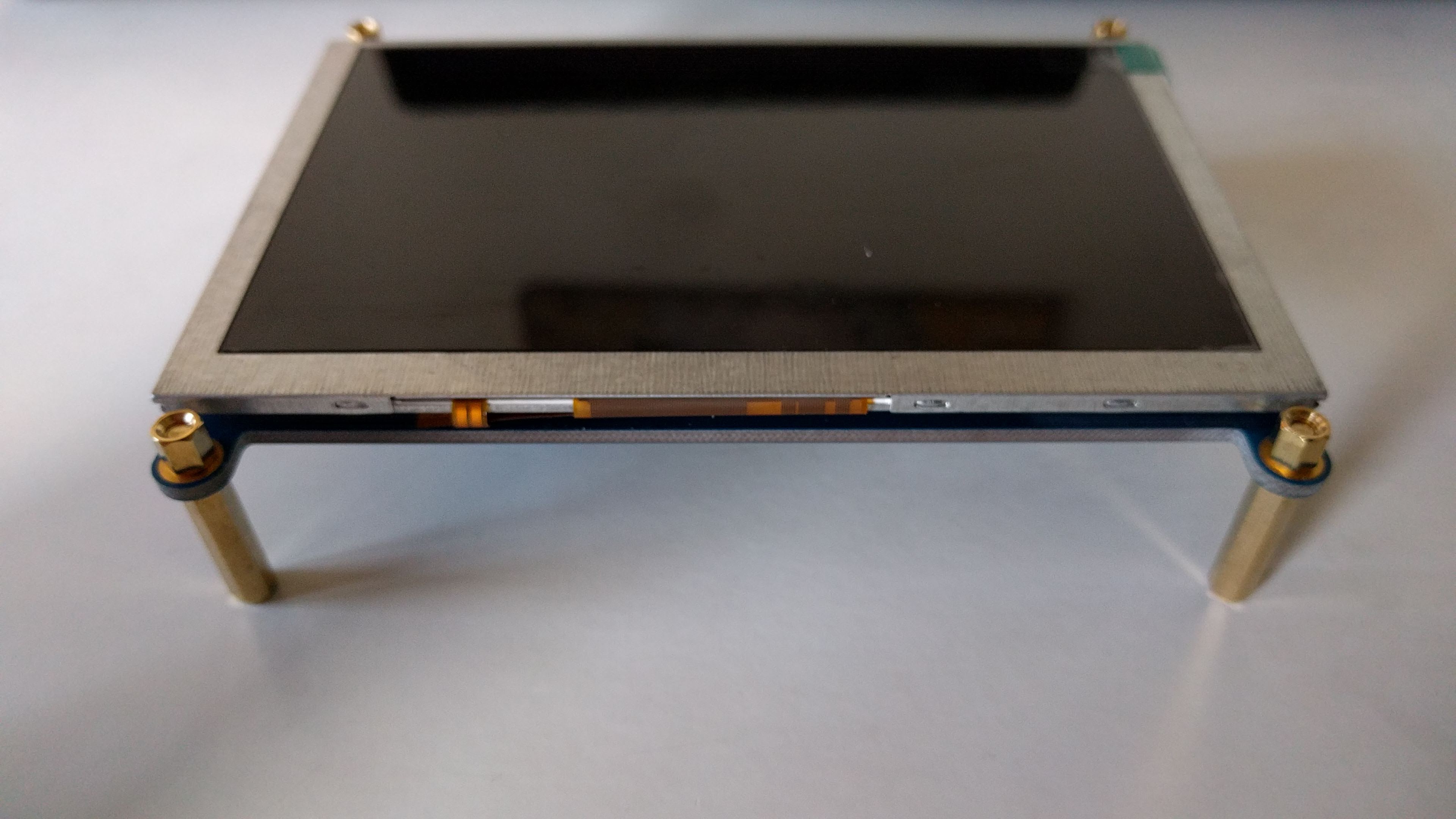
I played around with the spacing a bit. Early on I had realized that I needed a shorter HDMI cable, so I also ordered a 1' cable which seems to work alright. I couldn't find a flat one, and I probably should have gotten one with a 90 degree angled connector for the display side, but I'll deal with that later. The current one is workable.
From here I started to lay everything out and tracing the component outlines onto paper as a first step for designing the base. Things became a bit more complicated because I realized for usability the display should be angled towards the user. I briefly considered a hinged design, but abandoned it as too complicated. This step also revealed that to use the USB hub with the Pi Zero, I need to orientate the Pi to accommodate the hub's short cable, at least if I want the hub to fit snug along the bottom of the display. Here's what the rough sketch looks like:
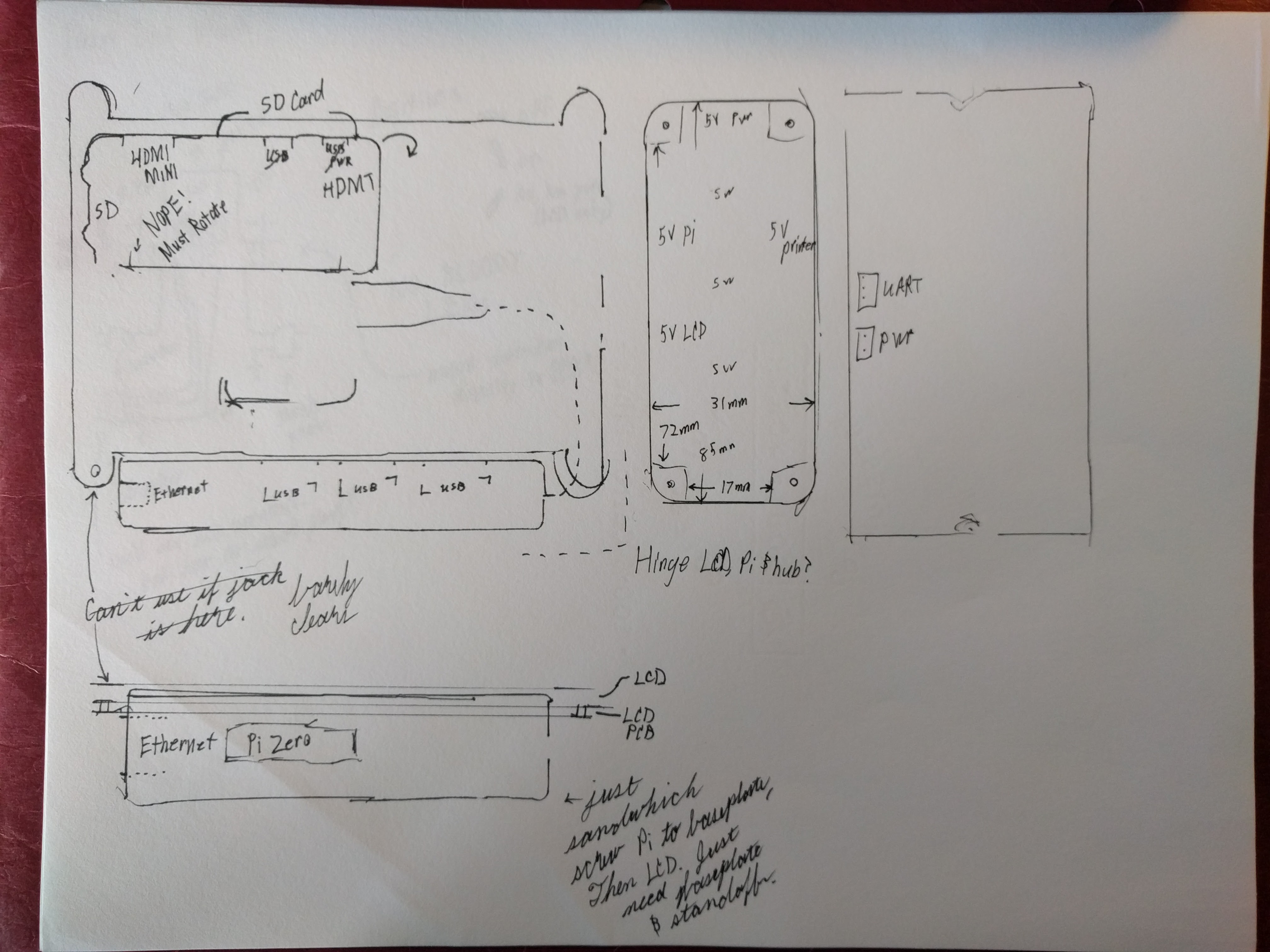
Note the "Nope! Must Rotate." I'm glad I saw that problem early. The outline used for the power distribution box is that of the aluminum box I threw onto my Amazon order to push it over the $50 shipping limit. It looks like it will work great... unfortunately I don't have any metal working tools or experience. In this diagram I tried to also capture relevant connectors / access points. For example, I'm going to orientate the Pi so that the SD card sticks out of the top of the display.
Next steps will be to design the base parts and order them.
Discussions
Become a Hackaday.io Member
Create an account to leave a comment. Already have an account? Log In.