 agp.cooper
New Motor Board Ready
Not unexpected but it took 4 hours to assemble.
Powered up, one wire mistake found (a direct short between Vcc and Gnd).
The ESP-12E fired up and ran the installed blink program, voltages nominal and drawing 100 mA with motors disconnected (2.65 A with motors connected and energised).
Added a small heat sink to the 5v regulator as at 100 mA it will burn 700 mW. While okay without a heat sink it will get hot.
Here is the board connected to the testbed: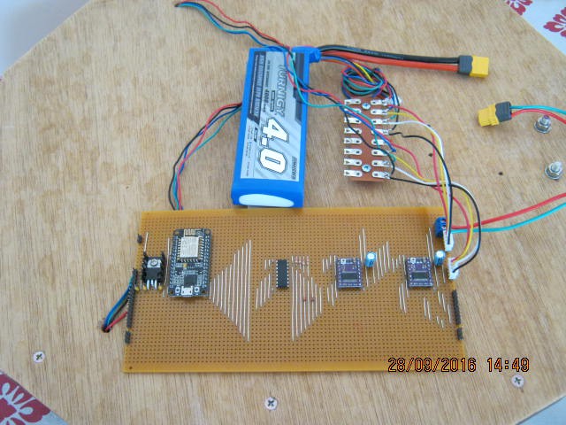
This board uses a PCF8574 (centre chip) to expand the IO. Both the DRV8825s and the ultrasonic sensors will be accessed via the PCF8574.
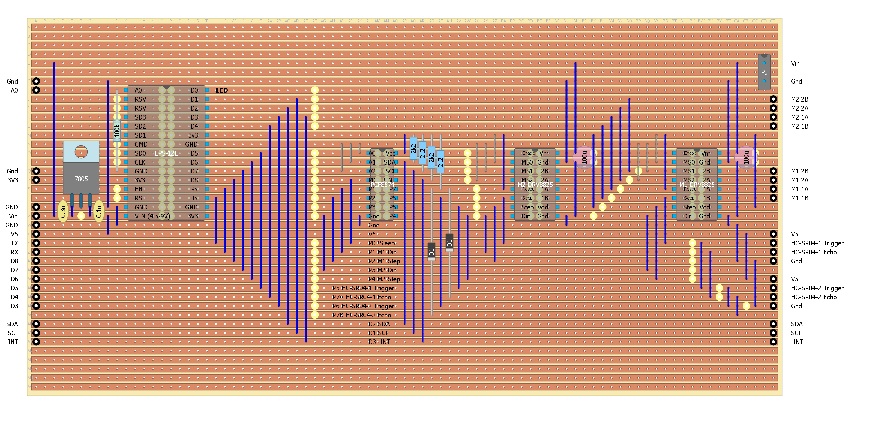
Here is the final strip-board design:
Software Updates
The basic I2C (Wire) is working, I can toggle the expanded port.
But I am having problems with the Serial code resetting the ESP-12E (the dreaded reset cycle) and my laptop!? If I slow the baud rate down to 9600 (from 115200) I get 30 seconds before my laptop resets. I did read something about this on the Internet with a fix but as usual cannot find the webpage again. The home made PulseIn() interrupt routine seems to be working as I get sensible numbers to my serial monitor before it blows up.
I tried no serial but with a variable period blinking LED (for the distance measurement) and it appears to work, but it still blow up if the sensor is too close or too far away from an object. So I would say it is ESP-12E.
So my options are to:
- Test the setup without Wire.
- Test setup With Wire, on an Arduino Uno.
- Find that ESP-12E Wire fix!
Results:
Loaded a example ASCII serial sketch and modified it to suit the ESP-12E:
On my desktop with a fresh Arduino IDE and USB driver:
- Worked on a Nano clone.
- Worked on an WeMos D1R1 (but had to remove the infinite loop at the end of the code and replace it with a blink else the "reset cycle").
- Worked on the ESP-12E (with the blink code).
On my laptop:
- Nano okay
- Wemos D1R1 okay
- ~5 seconds with the ESP-12E
Powering the ESP-12E with an external power supply:
- ~10 seconds with the ESP-12E
ARGH!!!!
Well I messed up my laptop trying to fix this. And this is not the first time I have messed up this laptop trying to fix USB problems. So now I need a RESET!
I needed a reset anyway because as fast as I make space available by moving my programs off the laptop it gets gobbled up somewhere else. I have one of those very cheap 32 GB SSD jobs (no hard disk). I guess I will have to put up with losing my Microsoft Office licence again! So this time I will take an image of the fresh install.
A day later, all done. All my programs reinstalled and 7 GB free.
The Nano worked and the WeMos D1 worked (I know I have to pre-install the CH340G driver).
The ESP-12E USB driver is not installed! Got it, the old CP2102 driver must have been bad, installed a new one and now it works properly.
I think its is time to take another disk image!
Last Night
Last night I got the sensors working with the PCF8574 chip. Realised the logic from the ultrasonic senors was inverted to what I originally thought. Inverted the PulseIn logic and now it works. But only with one sensor at a time. The diode NAND gate needs to be a diode OR gate. Okay, something for tomorrow morning.
Rebuilt the diode NAND Gate as an OR gate. A bit trickier than expected. You need to make sure that PCF8574 pins don't exceed their voltage ratings. Fired it up and fail. Time for the oscilloscope, checked the OR gates, works fine but the PCF8574 was generating some glitches(?) which were triggering the interrupt and freaking out the EPS-12E. The EPS-2E is nothing like an UNO, it is very sensitive about the code it runs and how the pins are hooked up. Everything I did to try and resolve the glitches made things worse!
Okay, rework the design for separate echo lines and push the DRV8825 !Sleep line off the PCF8574 and onto a real ESP-12E pin (I chose D8).
FAIL and FAIL and FAIL
It is now so bad I thought I had blown up the ESP-12E. It is pretty close to dead. Ordered two more ESP-12Es from ebay and then unsoldered the ESP-12E from the board. Plugged in a USB cable and it came immediately to life!? Okay check the board for shorts, nothing? Solder in some header pins to act as sockets for the ESP-12E, as soon as I plug it in, it dies. Check all the voltages, the only thing that looks suspect is the interrupt line.
Okay, unlinked the connections (wire links on the board) one at a time until it comes back to life. It was the connection between D8 and the DRV8825 !Sleep pins. Go figure.
Okay, Serial is working, the sensors are working. Now the D8 and DRV8825 problem.
Tracing the D8 and the DRV8825 !Sleep pin and checking the datasheet show that although the DRV8825 has a 1M ohm pull down resistor built in, the carrier has a 10k ohm resistor connected to the !Fault pin. Checking this pin I have linked it to the 3.3v power supply. This would make the !Sleep pin pull up. I have attached it to D8 that has a 12k ohm pull down resistor. Not good, especially for the EPS-12E. But why did I link the !Fault to the 3.3v power supply? On the A4988 this pin is Vdd and I lifted the design from the original motor board that used the A4988. So the solution is to unlink the !Fault pin from the 3.3v power supply.
Done and problem fixed, back to adding the motor controls and webpage.
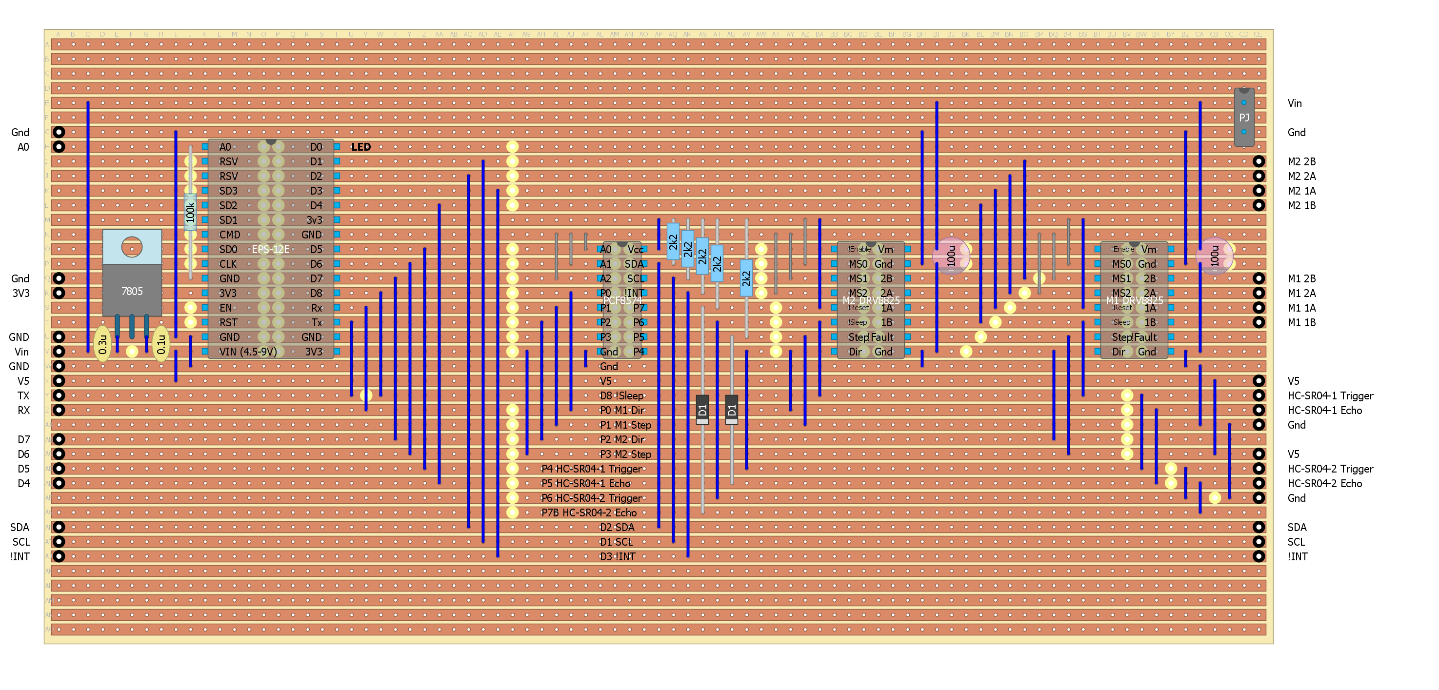
Here is the final Motor Board layout:
AlanX
Discussions
Become a Hackaday.io Member
Create an account to leave a comment. Already have an account? Log In.