 agp.cooper
Sensor Integration
Now that I have something that is basically working, I thought it would be time to think about how I am going to integrate four sensors to the ESP-12E.
The ESP-12E does not have eight free lines after allowance for the stepper control and other planned functions.
Generating in software a 40 kHz drive signal through I2C is not possible (too slow).
It seems like an ideal job for a ATTiny (slave) using I2C to communicate with the EPS-12E (master).
I that case having an LM567 and an ATTiny85 would be a bit of over-kill.
Why not simulate the Phased Locked Loop (PLL) in software on the ATTiny85 (it is something I have previously researched).
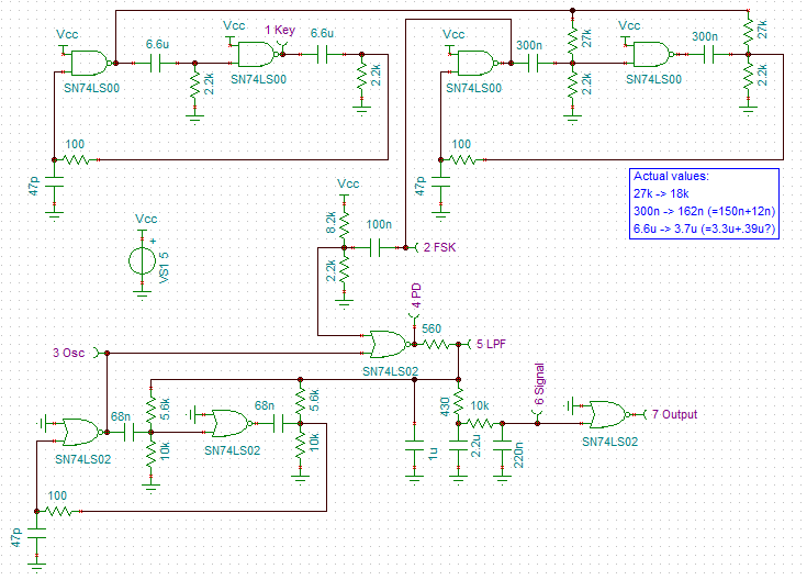
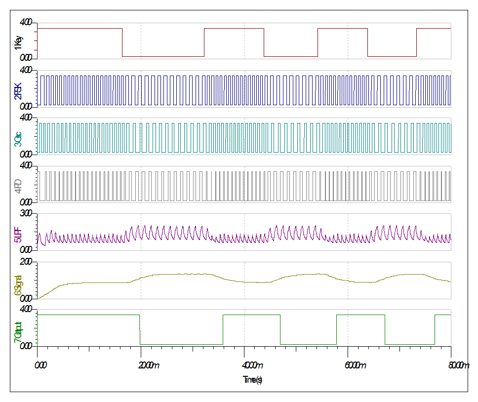
While I am thinking of it, here is my DIY PLL (hardware design using LS-TTL, the actual PLL is the 74LS02 at the bottom of the schematic (beginning with the 2_FSK probe) - yes it is that simple):
Another option would a Discrete Fourier Transform (DFT).
A search of the Internet suggest Goertzel algorithm would be a very good choice (someone has even written an Arduino library!).
Here is the algorithm:
double goertzelFilter(int samples[], double freq, int N) {
    double s_prev = 0.0;
    double s_prev2 = 0.0;
    double coeff,normalizedfreq,power,s;
    int i;
    normalizedfreq = freq / SAMPLEFREQUENCY;
    coeff = 2*cos(2*M_PI*normalizedfreq);
    for (i=0; i<N; i++) {
        s = samples[i] + coeff * s_prev - s_prev2;
        s_prev2 = s_prev;
        s_prev = s;
    }
    power = s_prev2*s_prev2+s_prev*s_prev-coeff*s_prev*s_prev2;
    return sqrt(power)/N;
}
(source: Efficiently detecting a frequency using a Goertzel filter - Wilfried Elmenreich)
Note: I modified the return value for rms of signal voltage.
Going through the calculations for an ATTiny85, 25 samples at 125 kHz (K=8) has a centre frequency of 40 kHz and will take 200 us (i.e. 8 pulses). The bin/band-width would be 5 kHz. The 8 bit (0-5v) ADC has a voltage step of about 20 mv.
On the multiplexing problem
A CMOS 4052 (2x4 analog multiplexer) or equivalent would work well here.
The pre-amp could even be on the MPU side of the multiplexer but then shielding of the inputs would become necessary - perhaps not!
Only one analog pin and three digital (output) pins would be required for four sets of sonar range finders (easier than using four ATTiny85 and I2C).
So interface directly to the EPS-12E is a good option.
Need to check out the EPS-12E ADC.
No, the conversion speed is about 83 us (12kHz) but OP report less in loop{} (about 8kHz).
Found an external SPI 4/8 chanel ADC (MCP3004/8) which looks interesting and fast enough (75 to 200 ksps depending on the voltage).
I need to see if a digital version would work for this application.
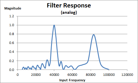
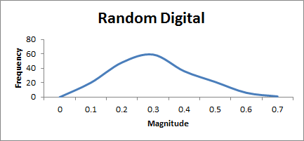
Simulation of Goertzel Algorithm
Wrote a short C program and plotted the results in Excel.
Here is the analog filter response:
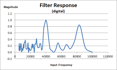
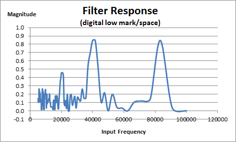
Here is the digital (0 or 1) filter response:
Testing with low mark/space ratio:
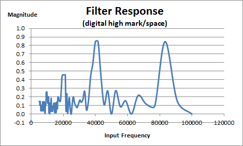
And with high mark/space ratio:
Although you could build a sonar range finder that just tested for any signal at the pin, the code is pretty neat in that it adds additional filtering.
Especially neat is the digital version version of the code.
Should be pretty easy to read a digital pin quickly (one source says 0.527 us on the ESP8266) on any MPU.
Not quite sure!
Not quite sure how to set up the analog/digital interface.
Here is one idea:
Cascade two amplifiers and offset the output (the input pin of the MPU):
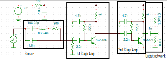
The gain is just less than 60dB:
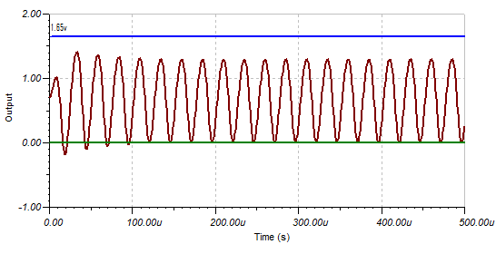
At 2 mv pp (at the signal generator) the signal is less than the MPU input trip point (assumed to be 1.65v):
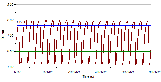
At 10 mv pp the signal will trip the MPU input:
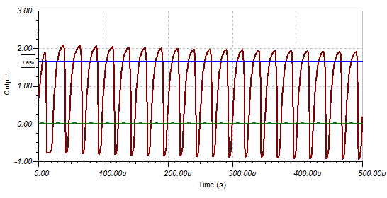
At 20mv pp the signal is not that much different:
Now the question is what should the gain be?
The gain depends on the background (signal) noise.
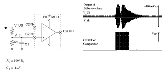
I found this image on the Internet:
(source: http://www.botlanta.org/ahrc-publications/sonar6)
This author has used an adaptive threshold but for his set up, a fixed threshold of 200 mv pp would work just as well (after removing transmit pulse).
The HC-SR04 (and others) uses variable gain (i.e. gain steps) with time.
A high gain bandwidth amplifier
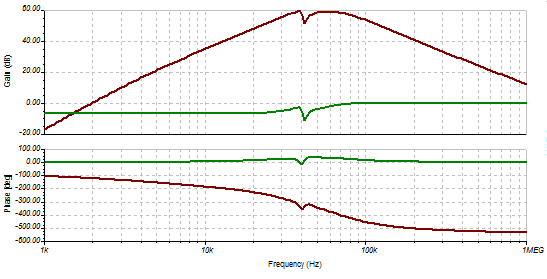
I spent the day designing a new high gain (60dB) high gain band width (60dB at 1MHz) for 3.3v. Here is the result:
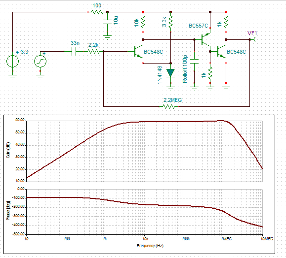
The output voltage (~2 v) is controlled by the diode drop.
The Rolloff capacitor depends on the application (between 100pF and 100nF), higher values are required for lower gains (basically the same as an OpAmp compensation capacitor but not as well behaved).
Here is the output for a 2 mv pp input signal at 40 kHz:
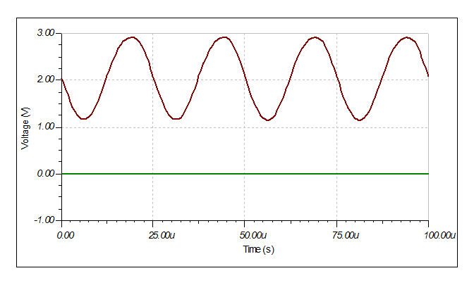
I wonder if it is stable outside of the simulator?
Checking the 3.3v logic trip voltages
In the above images I had assumed that the trip voltage was 1.65v (half the voltage supply). In fact the Vih is 1.55v and Vil is 1.4v (~150 mv hysteresis):
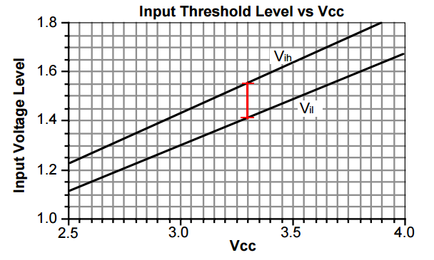
(source: https://www.idt.com/document/apn/124-33v-logic-characteristics)
Other 3.3v logic families are similar (the TI datasheet stated 1.5v for Vih and 1.4 for Vil (~100 mv hysteresis)).
Data Slicer
After a day or so I research I determined the approach take by others is a "Data Slicer":
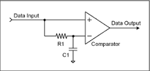
The RC constant should have a corner frequency (=1/(2*Pi*R*C)) approximately equal to the "pulse" frequency (=40 kHz).
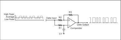
But how do you deal with noise (suppression)? After a few more days searching I found this circuit where the average DC voltage is offset:
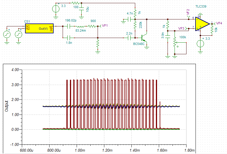
- 0% (100k) ~2 mV input signal threshold
- 50% (50k) ~4 mV input signal threshold
- 80% (20k) ~9 mv input signal threshold
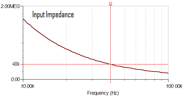
In the above design the transistor pre-amp has an input impedance ~4k and a gain of x18. The data slicer corner frequency is 40 kHz.
Conclusion
This is a very interesting approach and deserves further attention but since I have worked out why the HC-SR04 does not work and how to fix it. I will leave it for now.
AlanX
Discussions
Become a Hackaday.io Member
Create an account to leave a comment. Already have an account? Log In.