Close
0%
0%

TP4000ZC Serial DMM Adapter

USB adapter for cheap RS232 DMMs that translates into a "sane" serial protocol

Similar projects worth following
This is a USB adapter for TP400ZC and similar serial-port-equipped DMMs, which sound ideal for automated measurements. Unfortunately, these DMMs use an odd serial protocol, and without a true PC serial port, buffering in USB protocol stacks renders accurate programmatic measurements impossible. To fix these issues, I designed an adapter which translates the strangely-encoded output of the meter into ASCII-formatted numeric values and completely eliminates buffering issues. Importantly, the design guarantees that the data returned by the adapter was obtained *after* the request was made.

The adapter consists of three electrical components: a cheap ardunio nano clone, a 9-pin male D-sub connector, and a 4.7k resistor. Software on the nano abstracts away all of the nonsense of the meter's protocol. The adapter fits neatly inside a 3D printed enclosure. The software and the hardware design (for the case) are all in the GitHub repo and under an MIT license.

I have a pair of TekPower TP4000ZC DMMs. I like them for a few reasons: they're relatively inexpensive ($36), have 4000-count readouts, run for a long time on AA batteries, and most importantly have RS232 output for automated measurments. There are a few drawbacks, however - one of them quite serious. I put this project together to fix the issues I have with these meters.

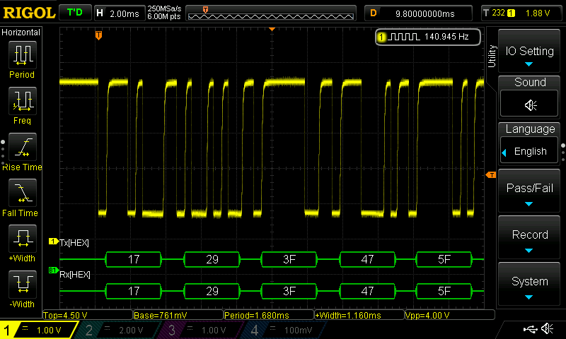
First problem: the serial output uses a bizarre protocol. Documented here, the meter continuously sends 14-byte packets encoding the state of the segments of the LCD display. This might be convenient if you wanted to re-create a 7-segment display on a PC-based GUI, but for collecting real data from the meter, it's just plain nuts. I wrote some C++ code to decode this protocol when I bought my first meter a few years ago, and hadn't thought about it much since.

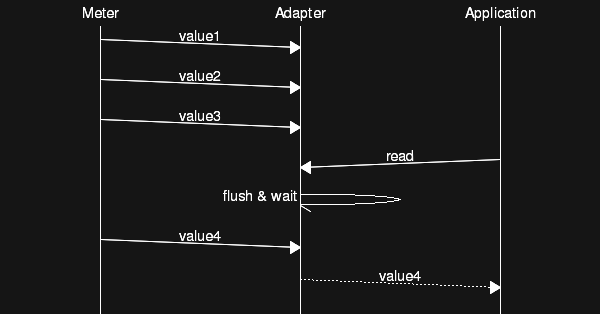
Second problem: the meter just streams these packets continuously. If you want to make sure you have the latest data, you have to continuously read the packets and be wary of any buffering in your system. For programmatic measurements, you need to be able to synchronize the meter readings with external events. For instance, a program might set a voltage going in to a device with a DAC, then want to read the output with one of these meters. If there's any buffering of the data, you may end up with a reading taken before the DAC was set: that's just plain wrong. The obvious solution is to flush the serial line before reading, but there's another problem: flushing USB-to-serial converters under linux doesn't work reliably (does it work anywhere?).

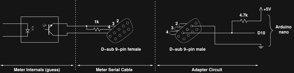
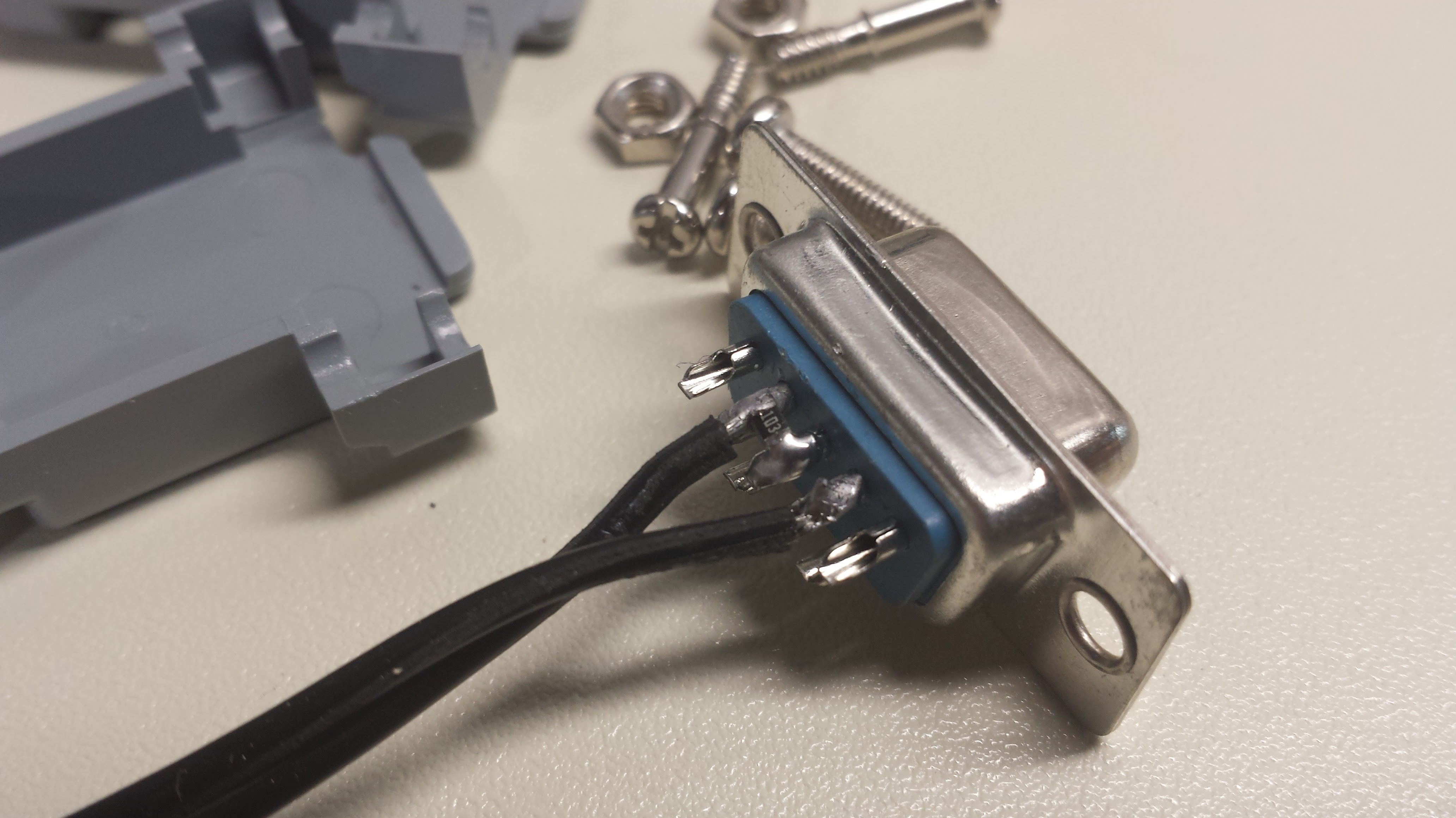
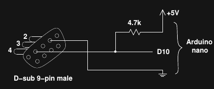
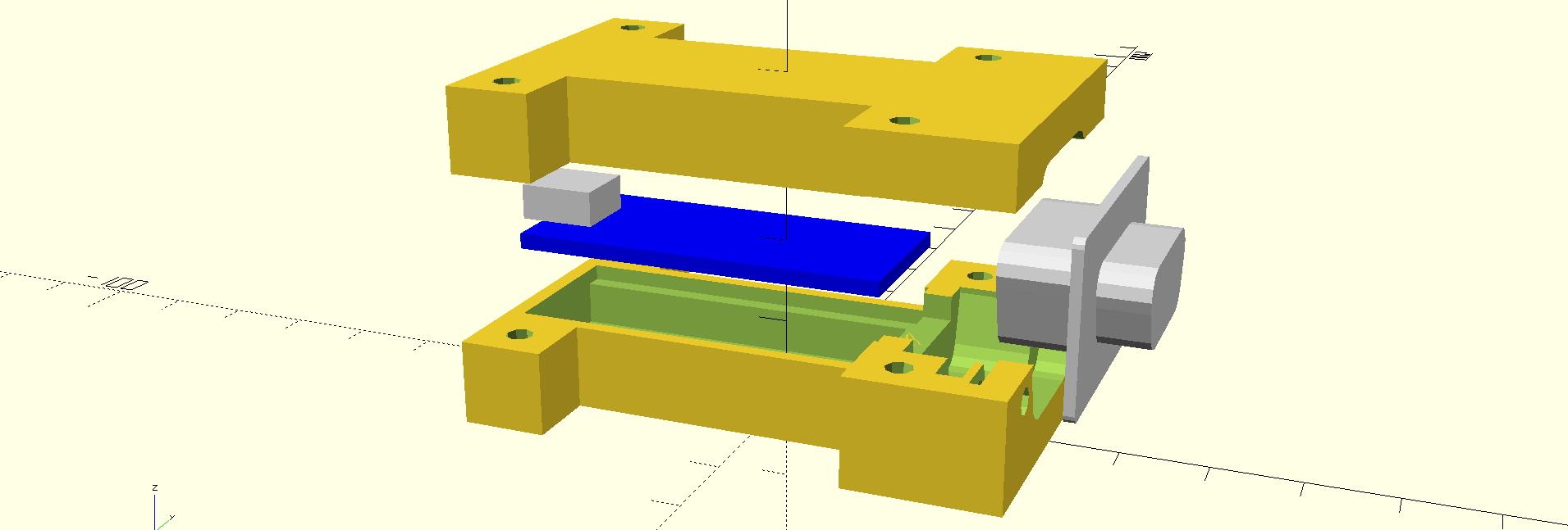
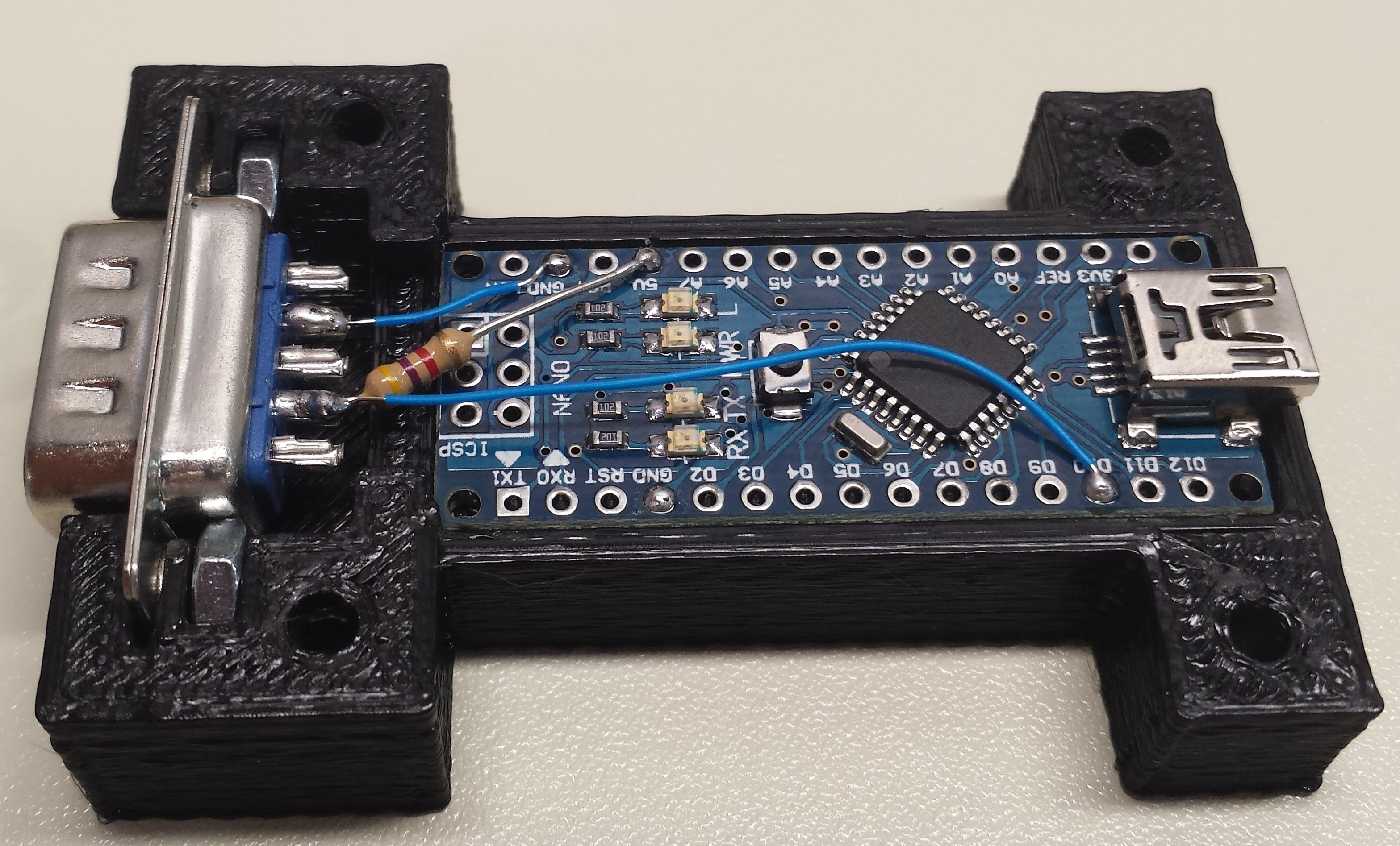
I struggled for a while with multi-threaded PC code that continuously read the serial stream (and tossed the results into the bit bucket) to avoid buffering issues, but it was a real pain and I could never get it to be 100% reliable. Last night, I finally got fed up and figured I could use a cheap arduino nano clone as a USB bridge and protocol translator at the same time. I got the thing working today - most of the time was spent designing the 3D-printed enclosure.

UPDATE 20160823: I think found a way to read these meters reliably using software-only (although the adpater is still useful for other reasons. Read the latest build log for the whole story. I haven't updated this details section or other logs to reflect the new info yet.

The details of the hardware and software are in the first build log. The protocol implemented by the adapter is discussed in another log. All the software and OpenSCAD design for the case are in the GitHub repo (MIT license).

I should note that a different way to solve this problem may be to use sigrok to interface with the meter. I haven't tried, but I suspect that would suffer the same issues with buffering. I figured if I was going to need a USB-to-UART bridge anyway (no true serial port on my desktop PC), I might as well throw the smarts in there, too, and avoid the buffering issue altogether.

  • 1 × arduino nano clone
  • 1 × DE9 9-pin male D-sub connector
  • 1 × 4.7k resistor
  • 1 × 3D printed case (top and bottom)
  • 4 × #4-40 machine screw 1" long (or M3 x 25mm long) Electronic Components / Misc. Electronic Components

View all 7 components

  • I get it now...

    Ted Yapo08/23/2016 at 16:06 0 comments

    It's funny how a few days after you "finish" a project, you realize all the mistakes you made. Since I've started documenting projects as I go, you, dear reader, get to watch me stumble :-)

    I realized last night why the serial adapter cable supplied with the meter is made the way it is, and how to get my original PC-only code to work correctly, so this adapter is not strictly necessary to operate these meters for programmed measurement. But, you still need a USB-to-serial adapter, and I thought of an enhancement for this design that I still think makes it worth using.

    Flow Control

    First, here's the diagram of the meter cable again. For the moment, ignore the right side of the figure.

    The meter has an opto-isolator inside that "shorts" the two wires going into the serial cable shell to pull the RD line up to a logical zero (crazy RS232 inverted levels). When the isolator is off, the RD line is pulled down to a logical one by a 1k resistor to the TD line, which is not used for data within the meter's protocol. This is a neat trick in that it preserves isolation between the meter and the serial port, but as I realize now, it's actually more than that. If you de-assert DTR, the data stops flowing. It might stop in the middle of a character, but when you start it back up, the receiver will regain sync on the next 14-byte packet. Using this, PC-based code can prevent buffering issues by only asserting DTR to take a measurement, then de-asserting again to stop the flow.

    I'll have to go back to the description and other logs and edit the places where I said it was impossible to ensure correct data without some kind of adapter, because it's certainly possible, and not even very difficult.

    Testing the idea

    So, this brings us to the right side of the figure. I think with a simple test jig, the original buffering problem can be replicated, and the software-only fix tested. Here's a picture of the assembled test jig, which sits in between the meter cable and a USB-to-serial adapter:

    As shown in the schematic, the RD, TD, and DTR lines are pass-through so the meter works as usual. The RTS and CTS line are connected as a loop-back, so that code on the PC can assert RTS, then know when the line has actually been asserted by reading CTS. The RTS line and signal ground are connected to the meter's inputs on the "voltage" setting. To test PC-only code reading the meter, you can do the following:

    1. set RTS either asserted/de-asserted
    2. poll CTS until it shows that RTS has actually been set
    3. read the meter using a candidate protocol
    4. check if the meter voltage reading reflects the known state of RTS (i.e., did we get stale data?)

    I ordered another meter for longer-term testing (and general use, since I typically have the first two in a dedicated testing setup for the forseeable future). When it comes later in the week, I can try this out. I'll put the PC-based C++ meter reading code in the GitHub repo, too.

    Device Enumeration

    So, what can the adapter do? Obviously, translation from LCD-segment maps to human-readable ASCII is still convenient to have in the adapter rather than on the PC side. You also need some kind of USB adapter to use these meters with a PC, too, and the adapter fits that role well. I think there's another enhancement that makes sense. One of the problems with many USB-to-serial adapters is that they end up mapped to different devices (linux) or ports (Windows) depending on when/where you plug them in. For tests with multiple meters (I'm currently using two of them), this is a real pain: each time you re-arrange the test setup, you need to check which device the meters came up as. Although some USB-to-serial bridge chips have a user-settable serial number which can be used to correctly map each port as it is connected, many (including the ones I have) do not. So, adding a mapping/discovery protocol to the adapter would make it pretty useful.

    Since the CH340 bridge used in many cheap arduino nano clones doesn't have a settable serial number, a discovery...

    Read more »

  • Protocols Compared

    Ted Yapo08/20/2016 at 14:35 0 comments

    Here's a comparison of the meter's serial protocol and that provided by the adapter. The meter continuously sends packets every 250 ms:

    In a system with un-flushable buffers (USB-to-serial adapters), an application can not be guaranteed of obtaining the most recent value. Even worse, it cannot be guaranteed of obtaining a value that was measured after the read request was made. This makes automatic measurement sequencing impossible.

    In contrast, here's the protocol implemented by the adapter:

    Upon receiving a read request, the meter flushes the small local receive buffer, then waits a period of time to ensure the sample returned was taken after the request was made. This ensures synchronization.

  • Does it work a million times?

    Ted Yapo08/19/2016 at 02:18 0 comments

    The biggest problem I wanted to solve with this project was avoiding stale data in automatic measurements taken with these DMMs. Since the DMMs continuously stream data with no way to synchronize with a specific point in time, any buffering can result in reading old values. If you have a program setting inputs to a device-under-test, then trying to measure the device, old data can really screw up your results. It's bitten me a number of times. So, I took care to avoid causes of stale data when programming this adapter. The adapter waits for a command from the host before sending any results. Upon receiving the command, the adapter continually flushes the nano's serial receive buffer for 250ms, which is the rate at which the meter sends samples. This discards any samples which may have been taken before the command was received from the host. Only then does the nano start listening for the beginning of a 14-byte packet from the DMM. It sounds good, but does it work? Could there be buffering in the meter itself that defeats all my precautions? I decided to do some long-term testing (like a million samples from the meter) to see if I could catch it sending bad data.

    Fake DUT

    I had a teensy 3.2 sitting on my desk, so I decided to use it as a synchronized tester for the DMM: the teensy sets the level on a digital output pin (0/3.3V), which the DMM must then read back accurately for a number of trials. Code on the teensy listens for 3-character commands from a python program running on a PC. The code sets state of pin D2 based on the first character in the command, then echoes the command back to the python code. The last two characters of the command are a sequence number to ensure no commands are dropped. When the python code receives the echo, it knows the pin state has been set, so it requests a sample from the meter. If the voltage read from the meter doesn't indicate the pin state that the command requested, the python code flags an error. Otherwise, the python code prints a log of this trial and starts again. Each pin state is randomly chosen with equal probability, and a 0-100ms random delay is executed between trials to try to expose any subtle timing issues. The python code is also running on my desktop which I periodically hammer on during the day, so that should add some more varaibility to the test.

    Here's the code on the teensy:

    // DMM tester: set pin2 high or low on synchronized control over serial
    
    int testPin = 2;
    
    void setup()
    {
      Serial.begin(9600);
      pinMode(testPin, OUTPUT);
    }
    
    // receive a string.  set or clear pin based on first char, then
    //  echo the string back for synchronization
    void loop()
    {
      char buf[32];
      if (Serial.available() > 0){
        int len = Serial.readBytesUntil('\n', buf, 32);
        if (buf[0] == '1'){
          digitalWrite(testPin, HIGH);
        } else {
          digitalWrite(testPin, LOW);
        }
        Serial.write(buf, len);
      }
    }

    and the python code run on the PC:

    #!/usr/bin/env python
    #
    # test serial DMM interface for buffering issues / stale data
    #
    import sys
    import serial
    import time
    import random
    import math
    dmm = serial.Serial('/dev/ttyUSB3', baudrate = 9600, timeout = 1)
    tester = serial.Serial('/dev/ttyACM2', baudrate = 9600, timeout = 1)
    # wait for arduinos to reset
    time.sleep(2);
    count = 0
    while True:
      count += 1
      if random.random() > 0.5:
        cmd = '1'
      else:
        cmd = '0'
      cmd += '%2d' % (count % 100)
      # output a random bit on pin D2 of tester, and wait for response for sync
      tester.write(cmd + '\n')
      response = tester.readline()
      if response != cmd:
        print 'Command error: (%s) - (%s)' % (cmd, response)
        sys.exit(-1)
      # read value from DMM and check if bit is correct
      dmm.write('n')
      value = float(dmm.readline())
      if ( (cmd[0] == '1' and value < 3.0) or
           (cmd[0] == '0' and value > 0.3) ):
        print 'Bad data error: (%s) - (%f)' % (cmd[0], value)
        sys.exit(-1)
      print '%d: (%s) (%s) (%f)' % (count, cmd, response, value)
      # sleep for 0-100ms randomly
      time.sleep(random.random() / 10)
    

    Results

    It's running now, producing output like this: ...

    Read more »

  • Just when I thought I was out...this project pulls me back in.

    Ted Yapo08/18/2016 at 14:54 0 comments

    I built a second copy of the adapter for my other meter - and guess what? It didn't work. In fact, the second meter didn't work with the first adapter, either (should have checked this before). Turns out I had mis-interpreted the analysis of the interface circuit inside the meter, and come up with a bad solution to interfacing the thing with the nano. I re-worked the interface so it's a lot more robust with both meters, and updated all the project text and images (this took much longer than the actual fix).

    Anyway, it works well with both meters now, and the electrical interface makes a little more sense.

    So much for my hack-a-day rate. I'm down to a hack-every-two-days now. :-(

  • Thoughts on the Meter Interface

    Ted Yapo08/18/2016 at 12:23 0 comments

    I think I figured out why the meter uses an odd physical interface: isolation. Right on its face, the meter says it can handle 600V max. You don't want that kind of voltage around RS232 wiring for the safety of personnel and equipment, so I'm guessing there's an opto-isolator in the mix like this:

    Isolation would certainly explain why the meter can't generate its own voltages for signaling (excepting the use of photovoltaic isolators, which are most often seen in low-speed MOSFET drivers).

    Recent Updates

    I made a few updates to the code and case last night, so if you cloned the repo, you probably want to do a pull.

  • Construction Details

    Ted Yapo08/17/2016 at 20:39 1 comment

    Hardware

    I couldn't detect the voltage levels used on the serial interface coming out of the meter. When I took apart the connector shell on the cable shipped with the meter to see what the heck was going on, I wasn't sure if I should be impressed or horrified:

    there are only two wires going to the meter. A 1k SMD resistor is soldered between the RX and TX lines as a pull-down for RX (the meter is transmit-only so TX is always asserted with a negative voltage by the host), and the DTR line (assumed held high by the host) is switched to RX by the meter to raise the signal line. Note that there is no connection to ground! This image is from the inside of the supplied cable, but you don't need to disassemble it or modify it in any way to use my adapter - just marvel at its brilliance (or stupidity).

    A little tinkering, and I came up with an interface to the arduino that produced nice looking signal levels:

    This circuit gives a good voltage swing with both copies of the meter that I have to test with. The low voltage is marginal for TTL levels, but well within the Vil spec for the ATmega328:


    That's it for the connections - a resistor and three wires to the +5V, GND and D10 pins on the nano.

    Case

    I designed a clunky-but-functional case for the adapter in OpenSCAD. Since I already had working C++ code to interface with the meter, the case design was by far the longest part of this project. I really wish 3D printers were faster; I iterated too many times on this design :-)

    Here's what it looks like in OpenSCAD:

    and here's the whole thing assembled into the bottom of the case:

    The embedded 4-40 nuts are a little tight, but they help hold the connector in the housing. With a little force, it will all fit. The screw holes are intentionally undersized - I cleared them out with a 1/8" drill bit (you might use a 3.5mm).

    Measure your nano before you print the case - I'm not sure they're all the same size, and you want a relatively close fit to keep the board from sliding around.

    Unfortunately, the screws supplied with the DMM serial cable are too short to reach the embedded nuts. If you want to secure the cable to the adapter, you'll need to replace the screws in the DMMs connector shell with longer 4-40 (or M3) versions. I've decided to skip it for now, and just won't pull on the cables.

    Software

    I had C++ code already written to decode the crazy 14-byte protocol, so porting it to the arduino was easy. It's about 300 SLOCs, so I won't post it here - you can check it out in the repo. The code continuously receives and decodes the packets from the meter, and scans for commands from the host. Commands consist of a single byte each. I've defined three commands so far:

    1. 'b' : report battery-low status
    2. 'u' : report reading with units
    3. 'n' : report reading only

    The responses to these commands are ASCII-formatted strings. Importantly, the adapter will only return a value that was collected after the command was received. Here's an example python program to test each command:

    #!/usr/bin/env python
    
    import serial
    import time
    
    dmm_port = '/dev/ttyUSB2'
    
    dmm = serial.Serial(port = dmm_port, timeout = 1)
    
    # wait for arduino to reset upon connection
    time.sleep(2)
    
    # get battery status
    dmm.write('b')
    result = dmm.readline()
    print 'Battery low = ', result
    
    # read numeric value only
    dmm.write('n')
    result = dmm.readline()
    print result
    
    # read numeric value and units
    dmm.write('u')
    result = dmm.readline()
    print result
    
    a typical output might be:
    tyapo@silicon software $ ./read_dmm.py 
    Battery low =  0
    
    -2.446e-01
    
    -2.446e-01 Volt
    
    
    I formatted the data in exponential notation with four significant places, which suits the 4,000-count ADC and range of the meter. You could easily modify the arduino code to change this format or add more commands as required.

    Next Up

    I think it's done. Let me know if you build one of these, or have any suggestions for improvement. Now I just have to print another case for my second meter.

View all 6 project logs

Enjoy this project?

Share

Discussions

Similar Projects

Does this project spark your interest?

Become a member to follow this project and never miss any updates