Close
0%
0%

Smart Bed Lighting

Motion activated bed lighting that only turns on between the hours of 9PM and 7AM. Lights your way automatically.

Similar projects worth following
Need to get up in the middle of the night? No more stumbling around in the dark or being blinded by bright lights with this device.

This devices uses a PIR motion sensor to turn on hidden lights under a bed to light your path when getting out of bed. An RTC keeps time and makes sure the LED strip will only be turned on during the desired hours.

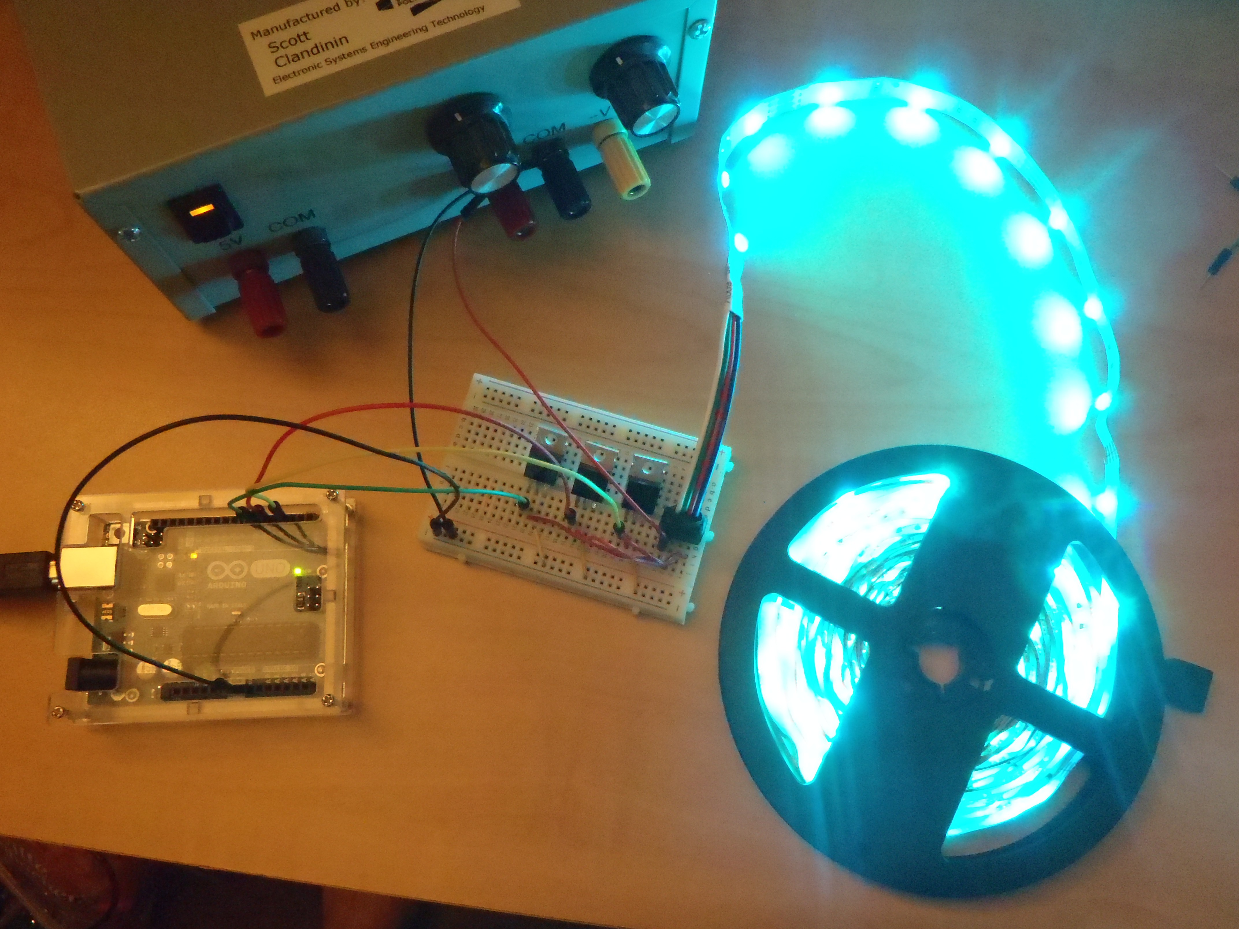
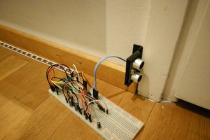
Step out of bed in the middle of the night and have an LED strip automatically light your way with a slowly changing light display. A motion sensor mounted on the wall overlooking the room triggers the LED's to turn on during the night.

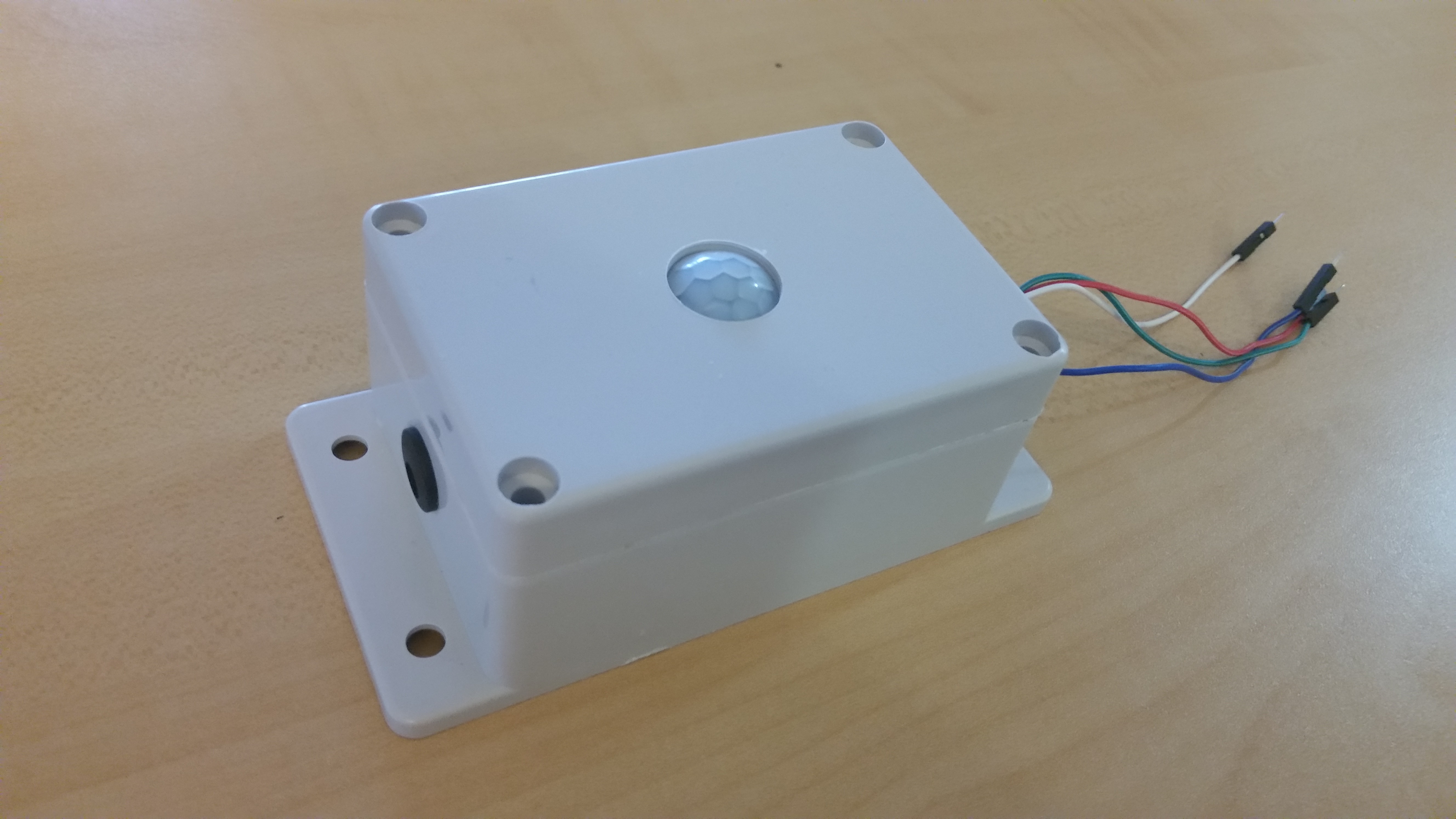
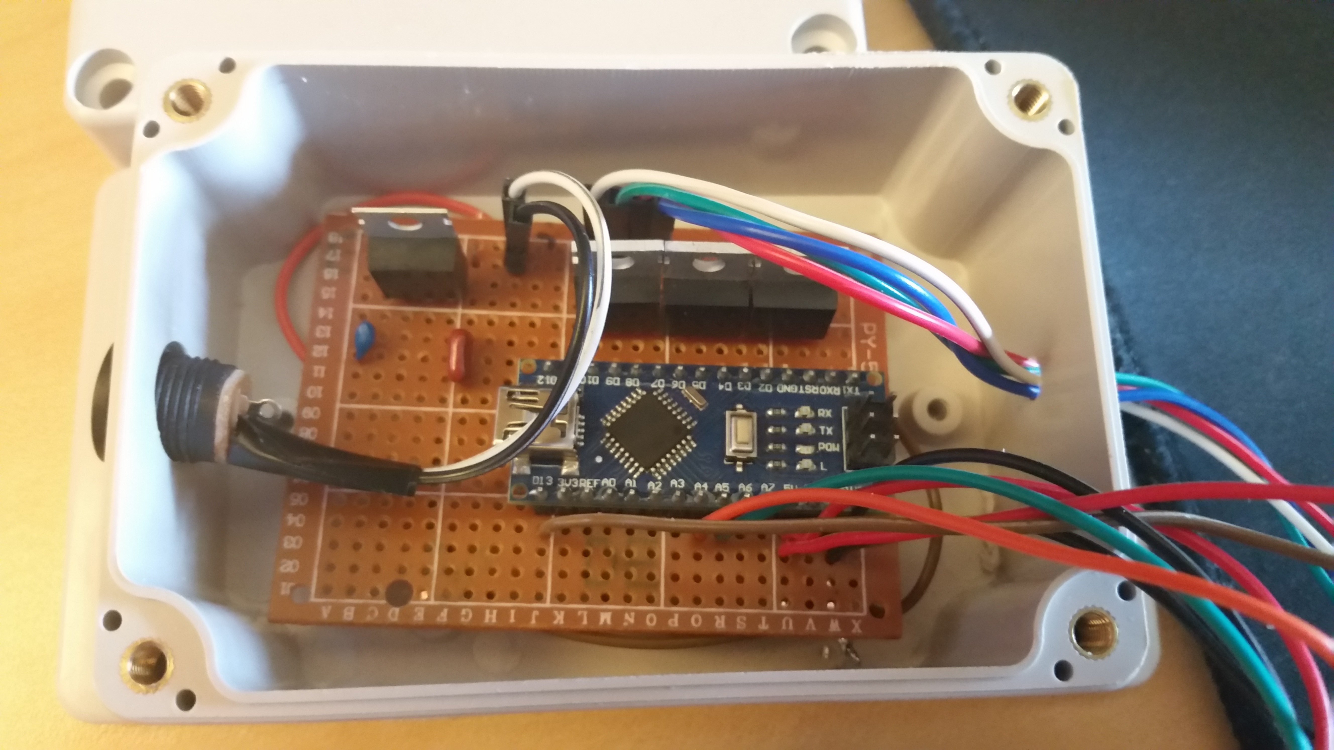
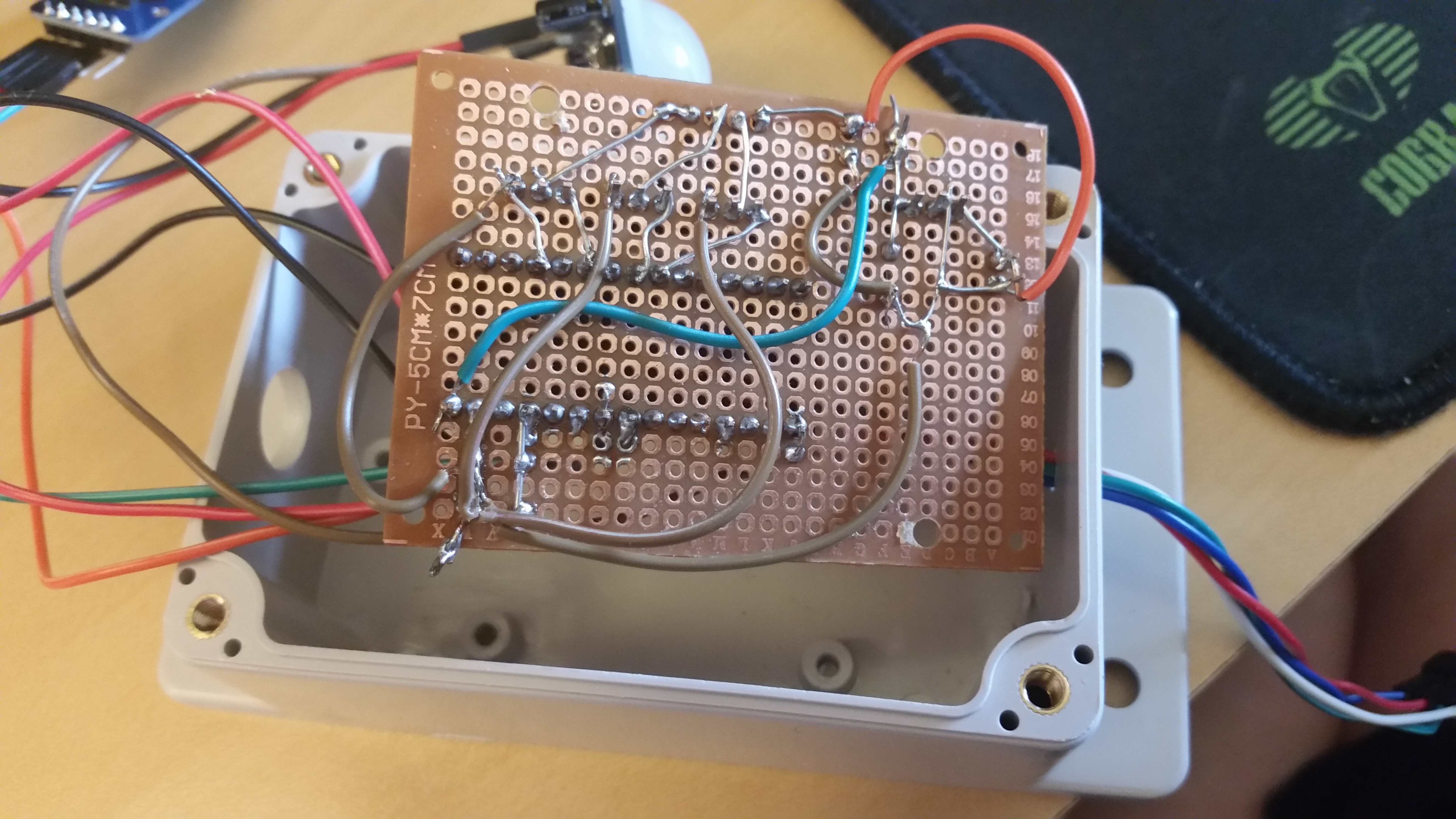
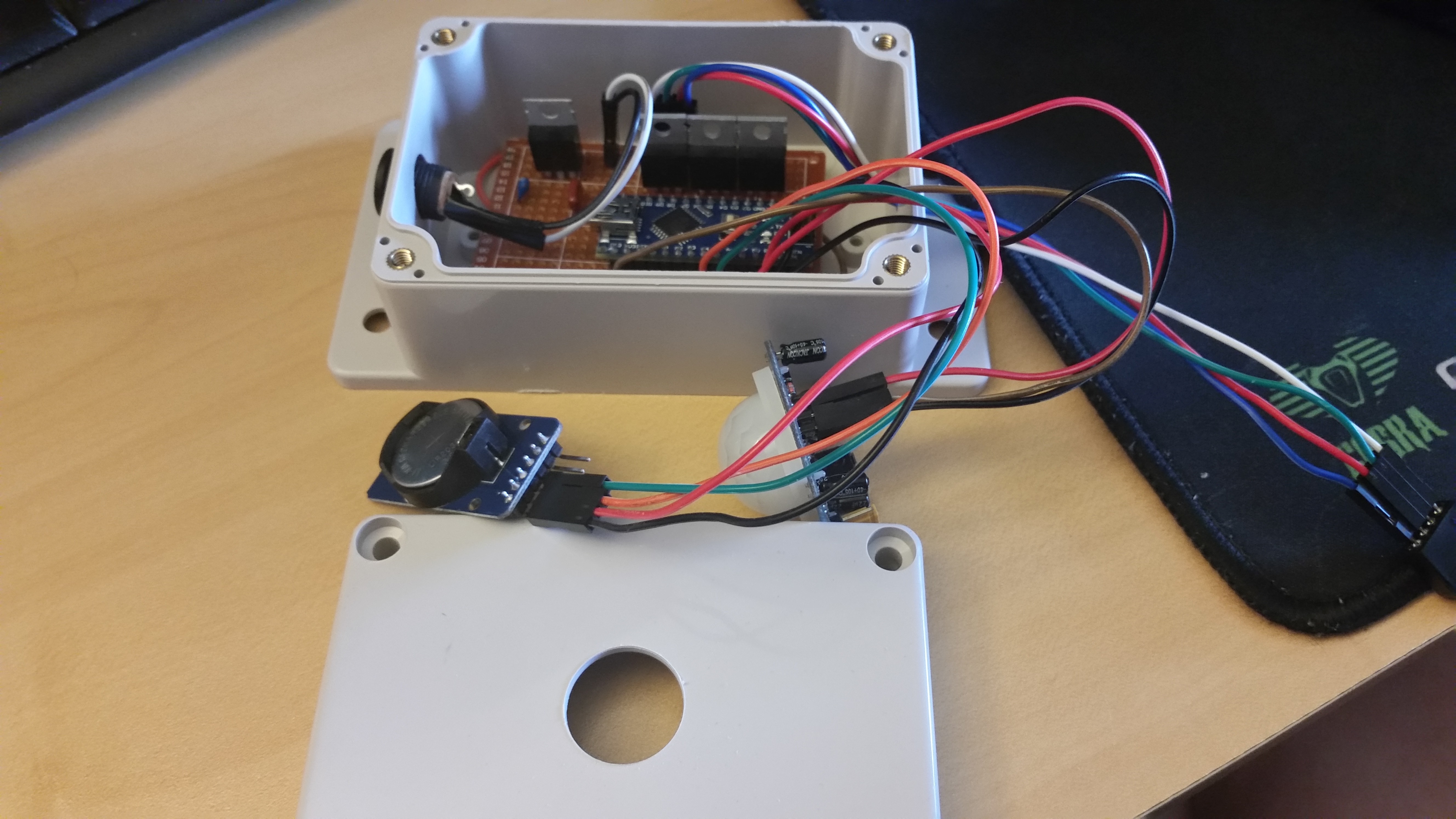
An enclosed Real Time Clock (RTC) ensures that the lights will only turn on between the hours of 9PM and 8AM. A small touch sensor on the bottom of the case can be used to test the lighting display outside of operational hours.

See project logs for full build details.

  • 1 × Arduino Nano
  • 1 × DS3231 RTC
  • 1 × HC-SR501 PIR Motion Sensor
  • 1 × LM7805 5V Linear Regulator
  • 3 × N-Channel MOSFET

View all 8 components

  • So it turns out a heat source under a PIR sensor is bad!

    Scott Clandinin12/13/2016 at 03:35 0 comments

    Who would have guessed?

    Heat Signature Representation 
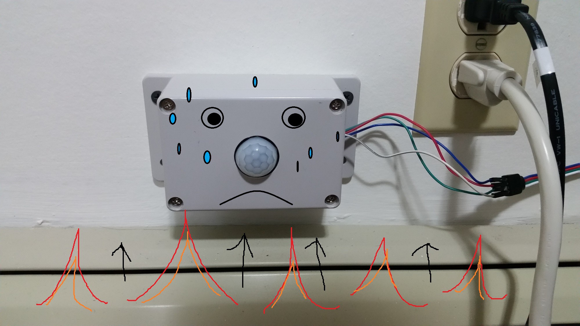
Heat signature representation
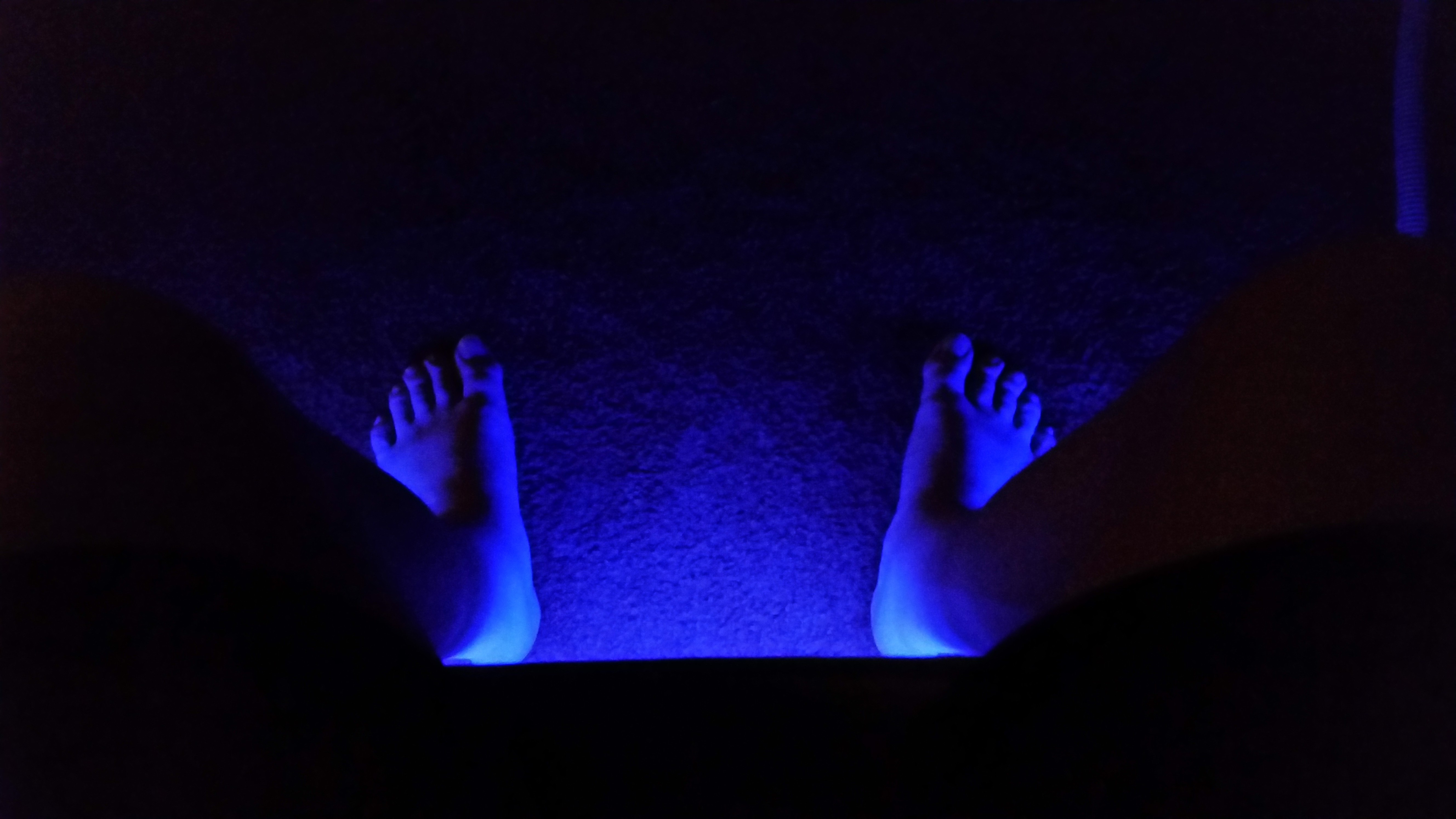

    See that thing at the bottom of the image? That is the heating unit that runs along the baseboards of my apartment for heating. In the summer/fall, my apartment needs little-to-no heating, so the design worked perfectly. But now that winter has come (the Starks are always right eventually), the unit would run constantly in the evening when the heat kicked on.

    I should have anticipated this before I chose a place for it, because it makes sense what it happening. The PIR sensor is sensing the heat and notices a varying IR background. I moved the unit from the wall and mounted it on the back of my nightstand about a foot away from the heat source. All working now!

  • An oversight regarding power supply

    Scott Clandinin10/30/2016 at 07:02 0 comments

    I just realized recently I made a silly mistake when I designed this project. I've been so used to working with the standalone ATMega and always needing a 5V regulator. When I decided to use an Arduino Nano for this project I overlooked the fact that it already has a built-in regulator.

    I was feeding 5V into a 5V on-board regulator, and since regulators always operate with a voltage drop, the voltage actually supplying the microcontroller was around 3.5-4V. Everything worked fine, but it would be more reliable at the correct 5V.

    It was a quick 5 minute job to pull off the external regulator I was using and re-route the power directly to the Vin pin.

  • It's a technology that can assist people

    Scott Clandinin09/09/2016 at 03:23 0 comments

    Okay so there are soooo many better projects for the "Assisting Technology" challenge, but this project may fit the requirements, so why not!

    This project, and motion based lighting at night in general is a pretty damn practical thing. With the technology being more available and home automation on the rise, I wouldn't be surprised to see this kind of technology in many house. I just made this for fun, but besides the basic "quality of life" benefits there are a few other important groups this can benefit:

    • Accident prone people
    • children afraid of the dark
    • people who can't see well in the dark
    • drunk people

    And even

    • drunk accident prone children who can't see well in the dark (a group often overlooked)

    Thanks to the availability and ease of use of modules and microcontrollers like Arduino, amateur home automation could be possible for anyone.

    • Project Completion

      Scott Clandinin08/27/2016 at 04:33 0 comments

      I went out and bought a new power supply (12V 2.5A) and was ready to mount the device and LED's!

      I mounted the main unit by my bedside near the ground. The LED strip came with an adhesive on the back, so I stuck that on the long side frame of my bed. Some tape was used as well to help keep the strip on the frame. And here is the result:

      Closing thoughts:

      This would be a great project for beginners who aren't too familiar with programming. With so many resources out there, I was able to use existing code for the PWM to the LED strips and a library for the RTC. The programming aspect of the project took about an hour or two.

      Hardware made up the majority of the project. I had to drill a few holes into the case for the power jack, the motion sensor, and the touch sensor. The main bulk of time was spent soldering components to the prototyping board.

      It was a fun little project that ended up being less than $50. Probably 90% of the cost of the project comes just from the power supply and the LED strip. Components like the Nano, motion sensor, and RTC are dirt cheap. My main warning to anyone interested in trying LED strip project is to make sure your power supply can handle the length of LED's you plan to light up. Don't make the same mistake I did!

      I've had this installed for a couple days now, and it's still a pleasant surprise whenever I wake up, step out of bed and see the LED strip light up.

    • RIP Wall Adapter

      Scott Clandinin08/22/2016 at 04:54 0 comments

      Welp, I made a rookie mistake. Was testing the device for a bit and it was all going great. Suddenly I hear a pop and the lights shut off. Whoops.

      I was using the wall adapter for this, which was rated to 2A. I was powering about 10ft of LEDs, which at peak would draw more than 2A. Since this was a cheap adapter off ebay, it didn't last long. I hadn't bothered to cut down the strip to the size I wanted (and that was safe for under 2A!).

      It's a real heartbreaker since it's pretty much ready to be installed. Any final touches will need to be done with my variable power supply again until I find a power supply with enough current output.


      Anyways, here's a look at what the final product may look like, just need to make the hole for the sensor a bit bigger.

    • Soldering and First Testing

      Scott Clandinin08/21/2016 at 21:34 0 comments

      Putting it all together

      90% of the time spent on this soldering the components together. I relied on dupont jumper cables to keep everything modular and easy to attach/remove key components. Basic cheap protoboard is a bit of pain to work with, but is great if you want to throw something together in a couple hours.

      You can check out the schematic on the previous project log to see what everything is. I used a 2A 12V power supply for this. These LED strips can draw a lot of current!

      For short jumps I used resistor leads, for long jumps, light cable.

      Here is everything all connected. Besides needing a larger bit to make space for the motion sensor, all the work on the case is done. It will be a tight fit, and I kept the wires a bit long, but it should be good to go. With all of it together I was ready to start testing.

      First Tests

      Things seemed to work great. I was able to set and then read the RTC. If the RTC hour value was > 20 or < 9 the micro would check the status of the motion sensor. While the motion sensor pin was high, the light show would go off. If the RTC hour value was outside of the above range, the lights would not turn off despite the motion sensor being triggered.

      Everything was going great until I heard a pop.

      To be continued...

    • Planning and Prototyping

      Scott Clandinin08/21/2016 at 21:08 0 comments

      There are 3 main things I need for this project in addition to a microcontroller (Arduino Nano):

      With so much existing code out there for these common devices, this is a really quick and easy project to make. The only time consuming part is the hardware side, soldering all the components onto protoboard and putting it all together.

      Here is the schematic:


      And the first test run of the LED strip:

    View all 7 project logs

    Enjoy this project?

    Share

    Discussions

    Martin wrote 09/05/2016 at 09:36 point

    What about just using a light sensor instead of the RTC? This would eliminate the need for a coin cell. Because probably you sometime will just forget about the coin cell in your lighting system and forget to replace it. 

    Another possibility would be to use a supercap. Your device is normally connected to the mains anyway, so this supply is just a backup for power outages.

      Are you sure? yes | no

    Scott Clandinin wrote 09/05/2016 at 23:47 point

    Definitely a couple good suggestions. A light sensor would have been the easiest/cheapest way to do it. My rational was that I had a couple RTC modules kicking around and thought it would be cool to try one out and restrict the hours of operation for the device.

      Are you sure? yes | no

    Similar Projects

    Does this project spark your interest?

    Become a member to follow this project and never miss any updates