0%
0%
3LE - linear laser light engine
a flat, modular and scalable light engine concept for stereolithography and its applications
 helge
helgeBecome a Hackaday.io member
Already have an account? Log in.
Just one more thing
To make the experience fit your profile, pick a username and tell us what interests you.
Pick an awesome username
hackaday.io/
Your profile's URL: hackaday.io/username. Max 25 alphanumeric characters.
Pick a few interests
Projects that share your interests
People that share your interests
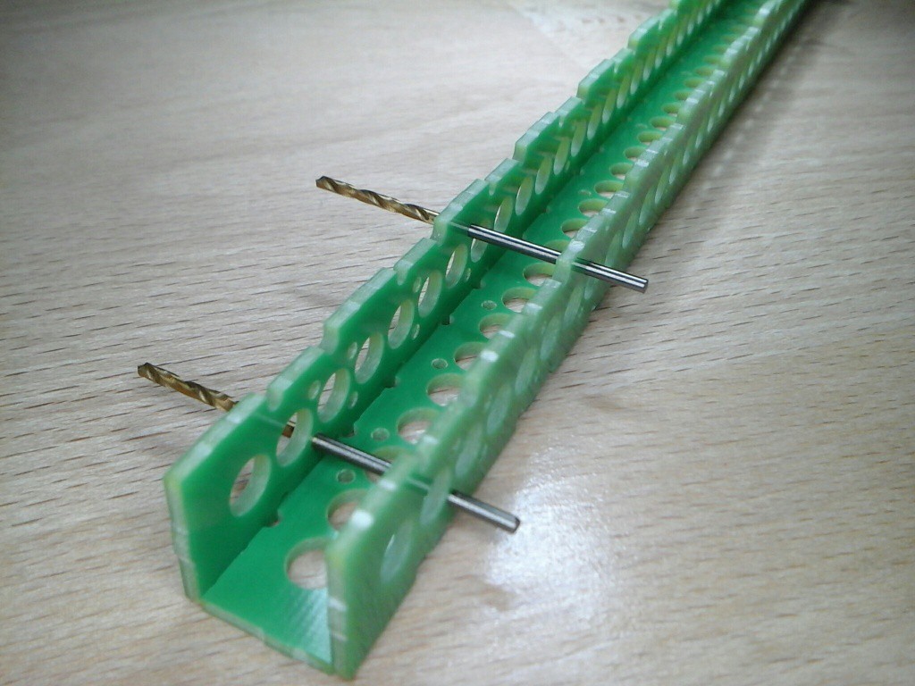
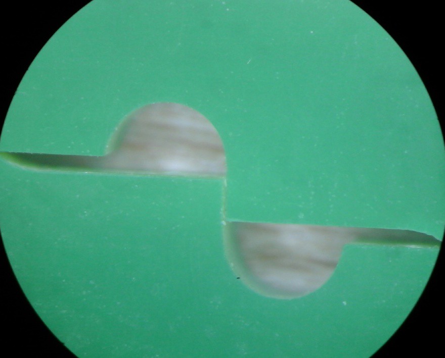
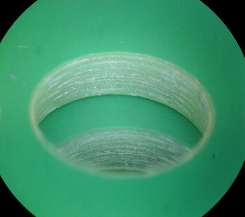
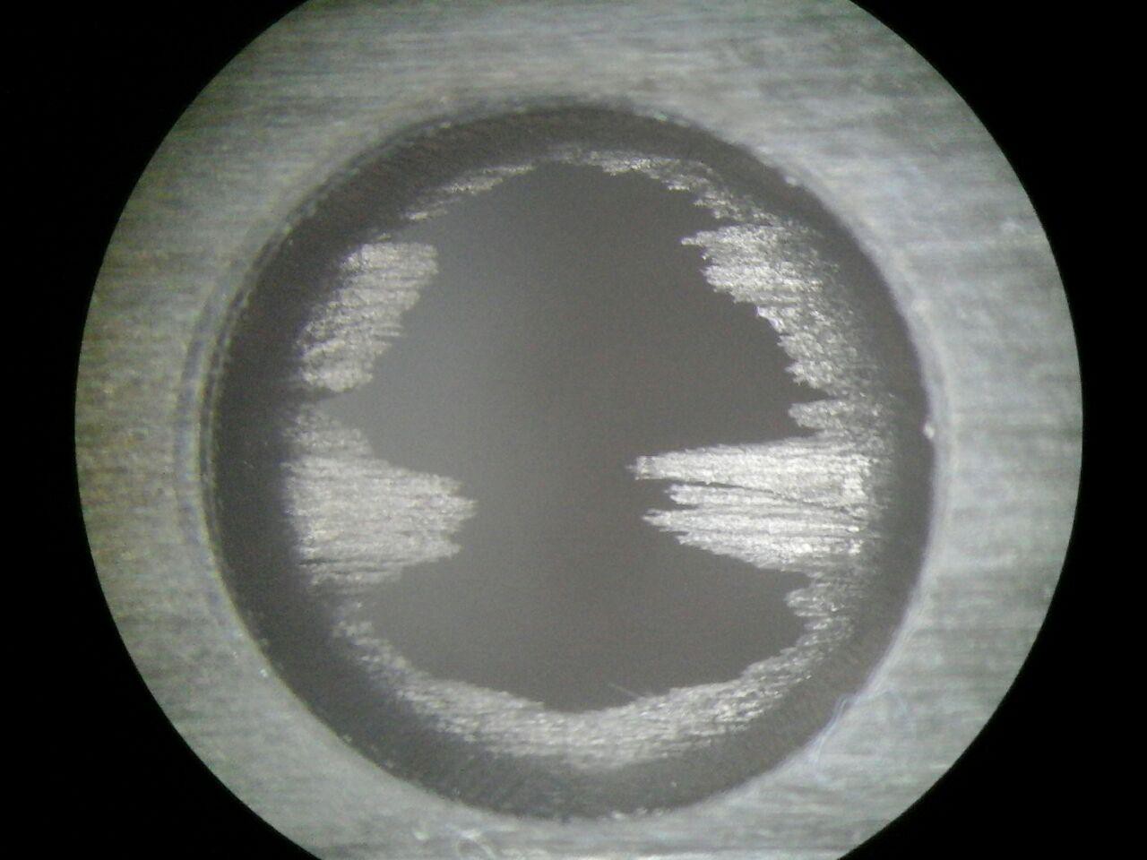
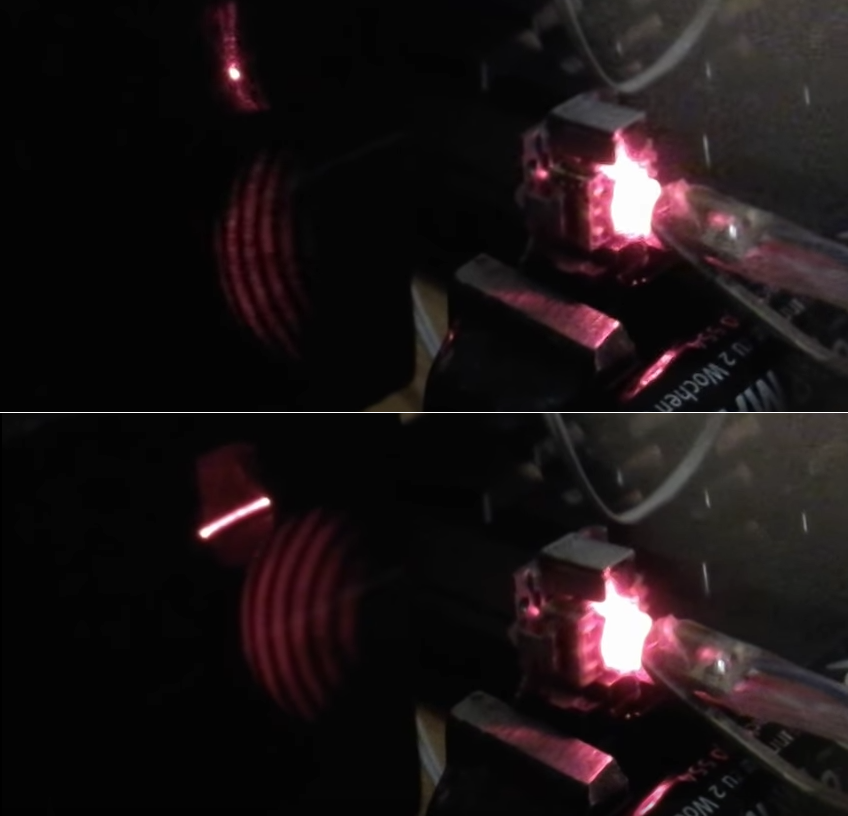
 This tube has a distinct weaving pattern and it feels like the top roving was a bit more resistant to ablation than the rest. Most importantly though, this is not a cylindrical hole by any standard.
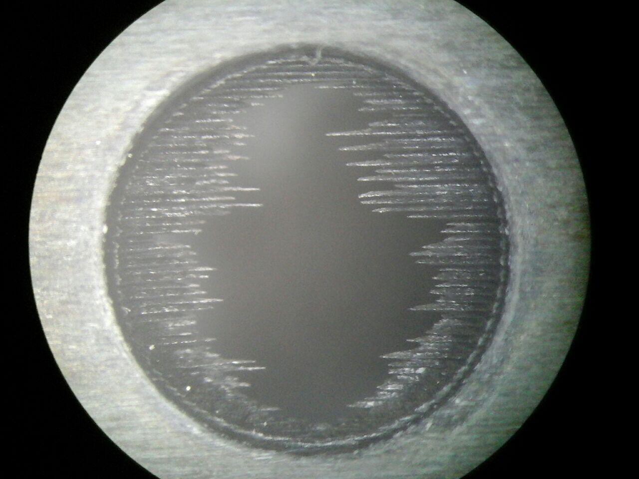
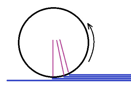
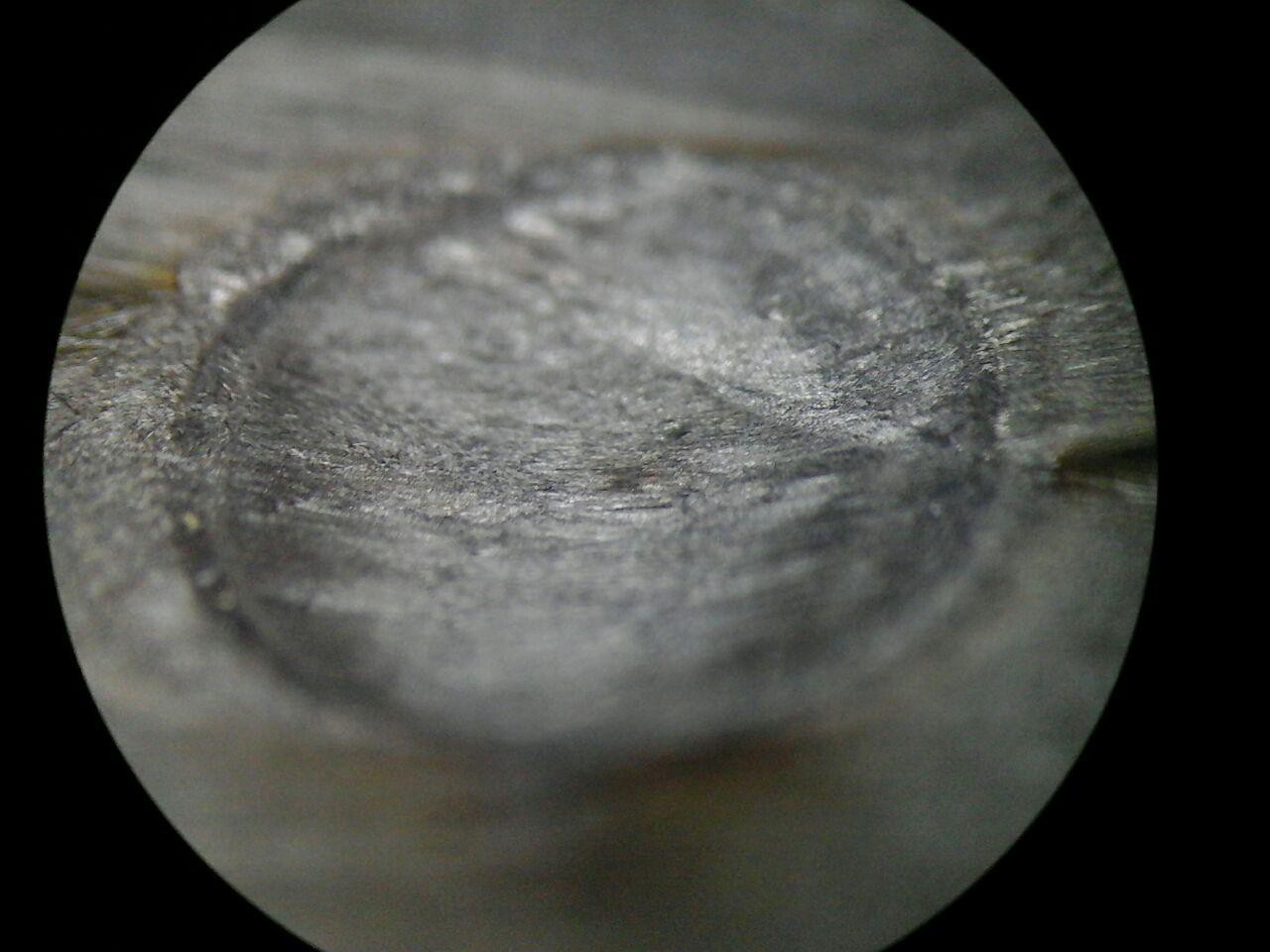
 After looking at the machine scribing a circle for 15 minutes and not getting anywhere I had seen enough. As for the difference in line width for x and y directions: either something shifted on me (I did reproduce the linewidth directionality though), the material ablates anisotropically or the laser mode is unstable (it jumped from being bright do being much less so, then back to bright over a couple of minutes). Maybe it even has something to do with anisotropic heat transport.
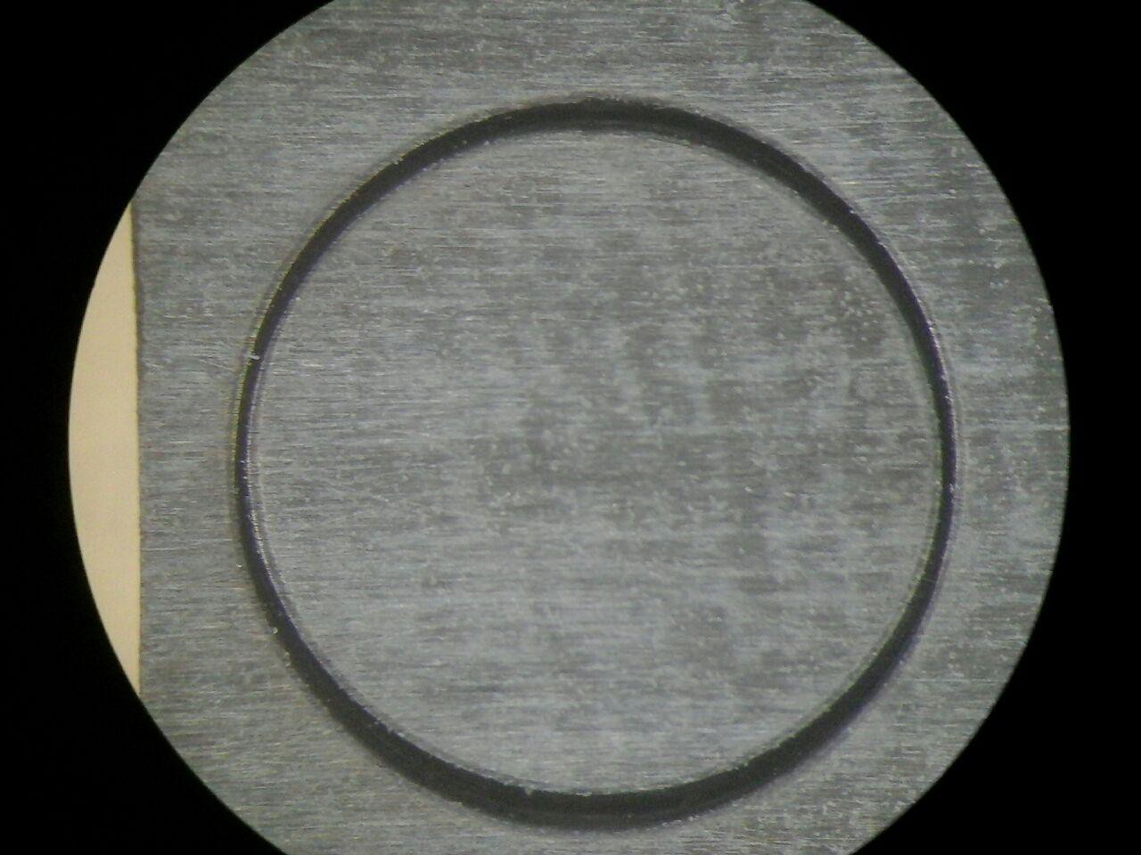

 Jason Cho
 Hexastorm
 FabLab München
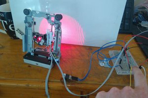
 johnowhitaker