 helge
helgeThe core of the design is the array of optical paths which have to be defined by precision pressing the laser diodes in a test jig. This should be easy enough since they can be powered and the optical performance can be monitored in a closed loop fashion.
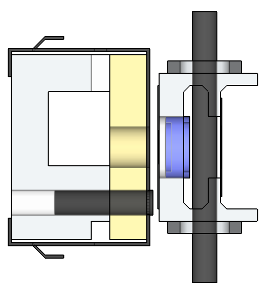
On the left, the cooling profile, 8x laser diode tile and spring clip are shown, on the right, a CFK profile with press mounted molded aspheres is shown, along with an anchor rod used for steering.
Calibated assembly has to be done once and can be automated to produce the segment modules. Each module has 8 LEDs, temperature sensors and an EEPROM with calibration values and temperature coefficients.
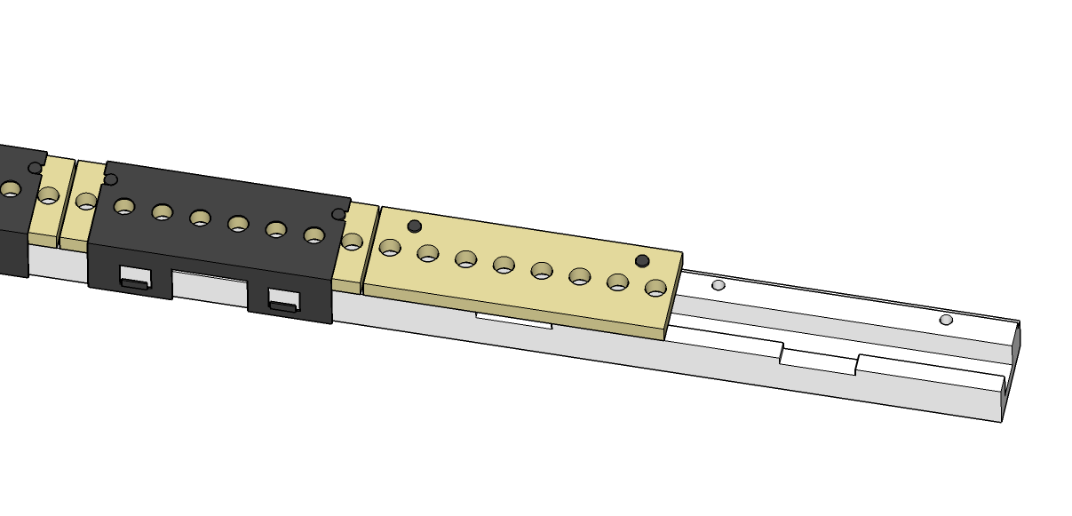
the LD sub-assemblies self align via dowel pins and are held down with spring clips. The profile is designe for forced air cooling or water cooling with a small OD tube.
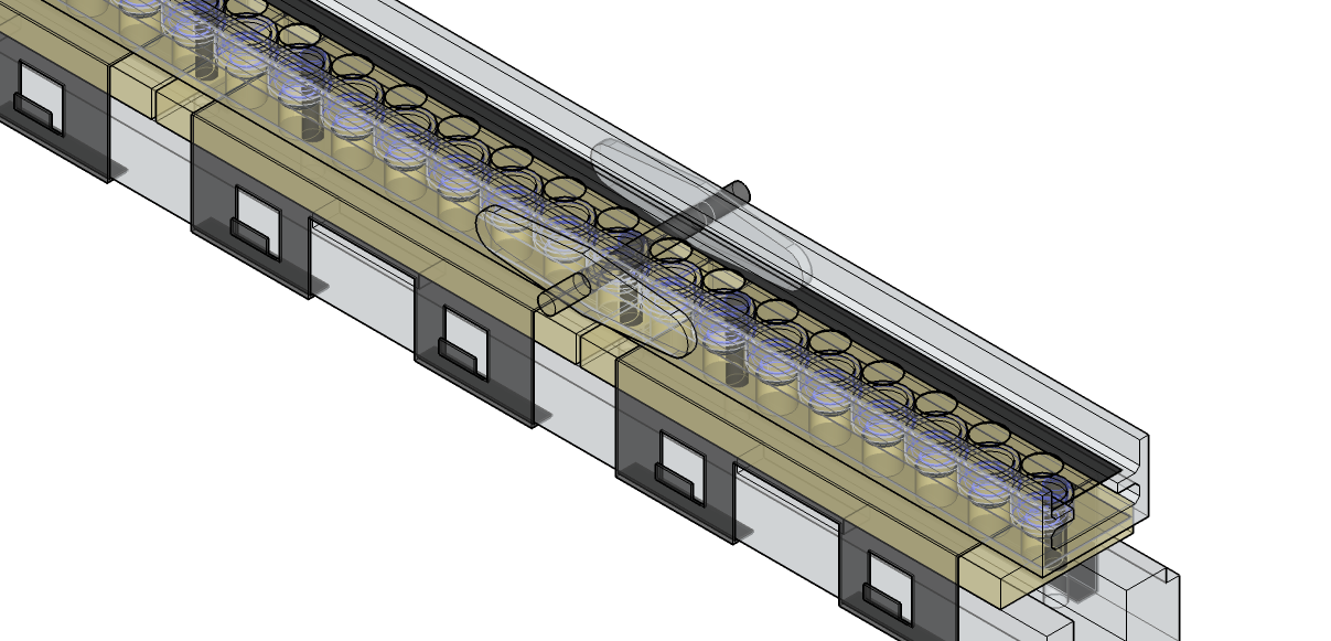
the anchor rods are located between two lenses and their beam paths. They are connected to a triangular U shaped segment (not shown). The upper point of the triangular piece connects to the anchor rods on both sides, its remaining to points are connected to piezo actuators. Their common motion moves the lens array up and down while their differential motion moves it around along its axis. There are two anchor rods and two pairs of piezo acutators respectively, also allowing a small dynamically controllable positive preload to avoid backlash.
I intended to use DRV2700 for the piezos (not suitable for piezo trimorphs without modifications...) and LDC1000 for precision position monitoring and closed loop absolute position control.
The position of the anchor rods is a thing in itself, see https://en.wikipedia.org/wiki/Airy_points but I guess it's more important to find points that don't dynamically coincide with nodes of the most easily excited beam vibrational modes.
Resilience and online calibration
Seems like I forgot to mention a few things.
Both the individual control over the emitters and the additional degree of freedom (note the two directions of linear motion and one tilt degree of freedom, which leaves another, more subtle one for clamping force / play) allow for a few gimmicks. Emitter grouping and sequencing however may be the single most important one.
Especially during prototyping not all laser diode module are guaranteed to be at the same height, maybe not even the single emitters. For maximum resolution, emitters can be calibrated and grouped by focus distance and then driven sequentially, re-adjusting the focus in between.
Emitters can also be grouped for simultaneous exposure when isolated emitters have failed. I've already mentioned that "dark strips" caused by failed laser diodes can be covered by their neighbouring emitters while increasing the stroke. This need not cause degraded resolution over the whole width when the scanning speed is decreased, allowing exposure to happen in a small stroke, small angle and high resolution phase, followed by a large angle coverage phase where exposure only happens locally where needed.
The fourth degree of freedom allows adjusting pre-load to adjust the backlash to zero as mentioned above. This allows to compensate for wear and avoid excessive forces on the bearing surfaces.
Discussions
Become a Hackaday.io Member
Create an account to leave a comment. Already have an account? Log In.