 helge
helgeWe did away with the "lightweight and sturdy" aspects of CFK for now due to manufacturing difficulties and opted for FR4 parts ordered as conventional PCBs.
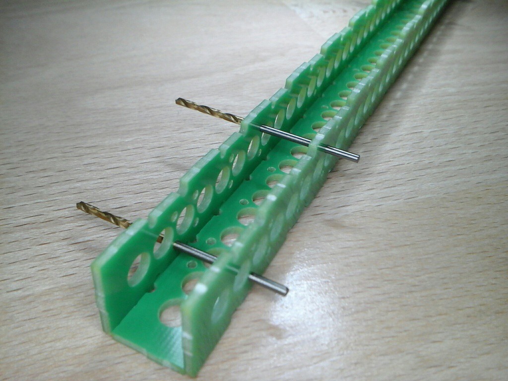
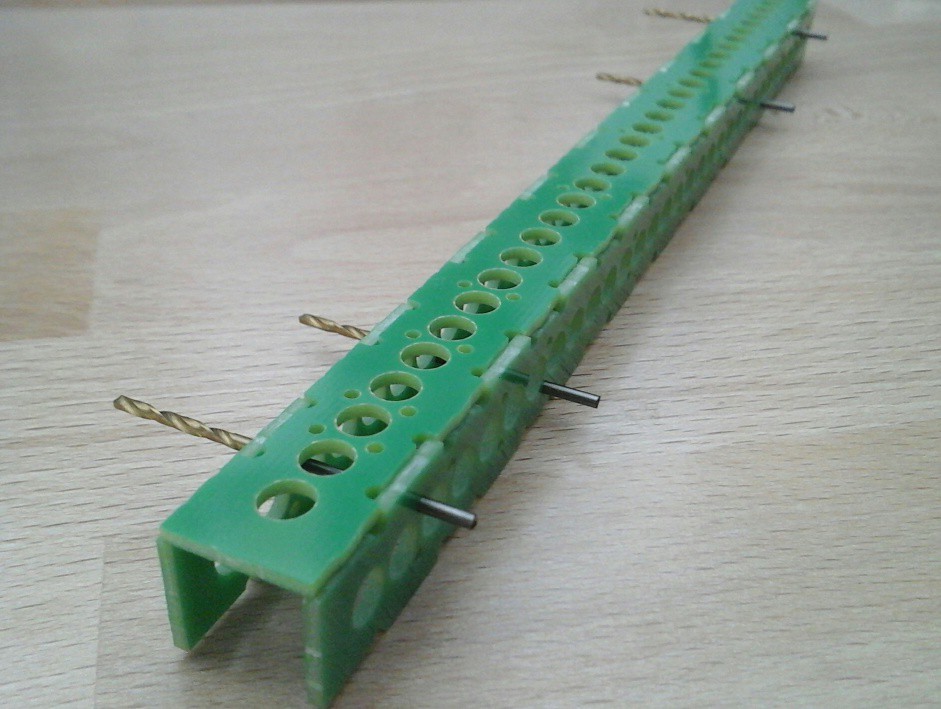
Three boards come together with a bit of epoxy glue and two 1.5mm dowel pins. Since I only have a pack of 1.5mm drill bits and a micrometer to check them I'm guesstimating the 1.5mm holes by feel to be 10-20µm oversize - 3 out of 5 drill bit shanks I used as ghetto pin gauges came out at 1500 +/- 5µm, one is about 30µm undersize and has a notably looser fit.
It's a pity they only provide 1.6mm FR4 so the three PCBs weigh in at 17.6 g (instead of 11 g) but we'll have to make do with that now.
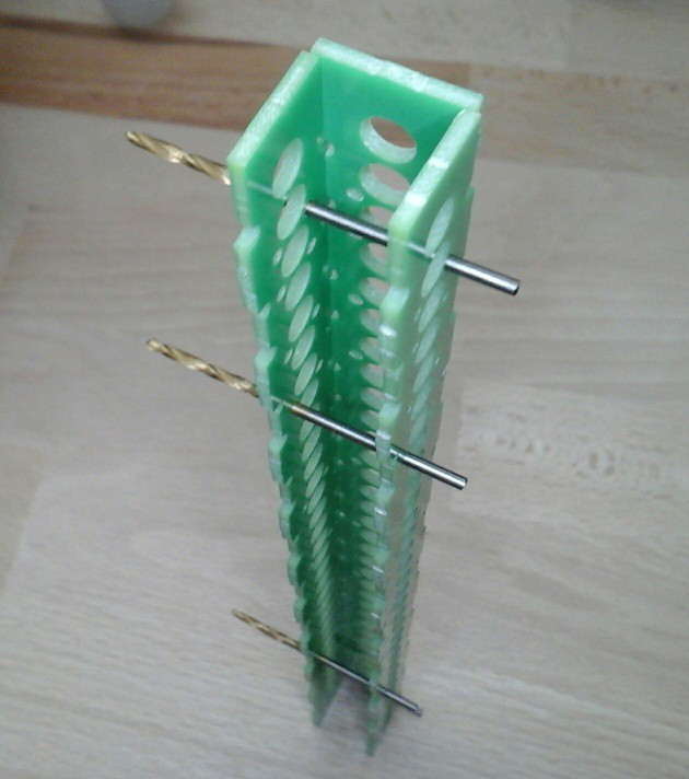
The overall tolerances seem good, with excellent repeatability (no problems fitting the tight tolerance pins through stacked PCBs). The smaller radius isolation milling is tighter than the PCB contour milling so the outside edges are not in spec. Luckily only the inset contours produce reference faces (upper board left, lower board right) so it's ok.
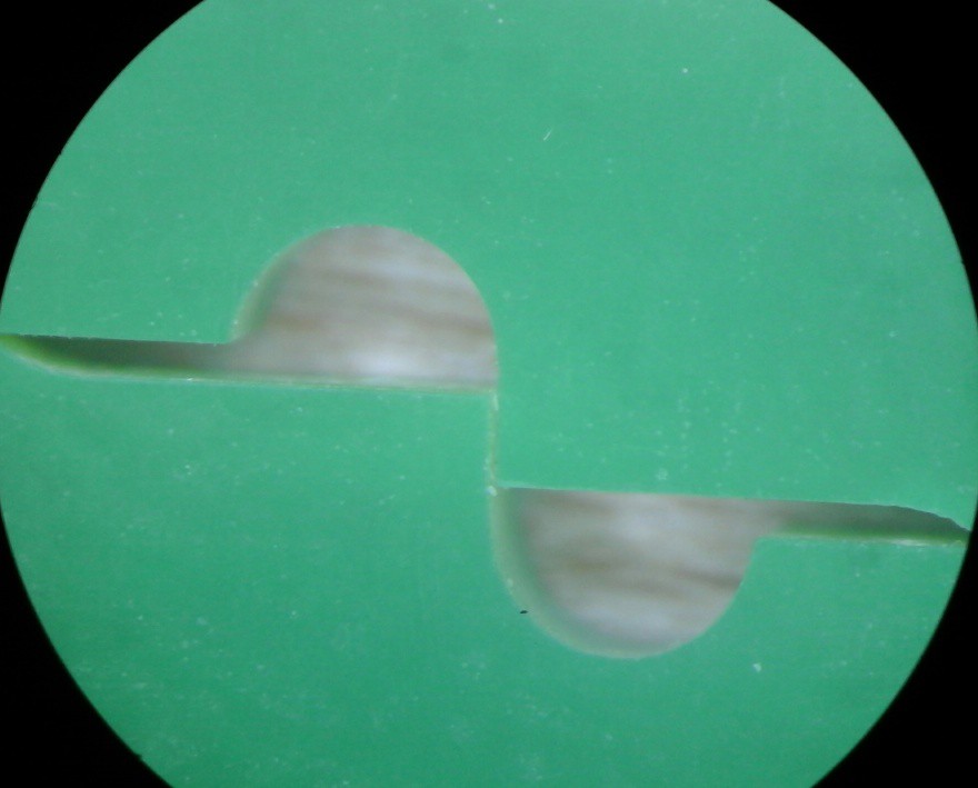
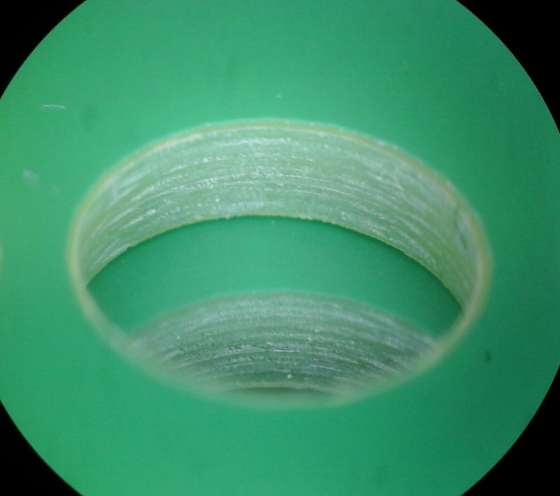
The holes for the molded lenses are milled, nice and round with minimal chipping and for what it's worth, the stopmask is properly aligned.
I think I'll wait until monday and get myself a 12mm aluminium plate to help with the glueing so the sides don't end up crooked.
Discussions
Become a Hackaday.io Member
Create an account to leave a comment. Already have an account? Log In.