 charliex
Last week we did the battery tests using the 800mAh "iPod' battery we have used before, it is cheap and easily available, the results were about two hours running everything, I posted the data earlier. That is not great, the conference is 3 days usually ( 4 days this time ) and two hours means charging a lot of batteries.
What to do ? Well I'd ordered some various 18650 batteries last week and chargers just to test them, much to my amusement they're called "UltraFire" with an icon of a fire and a claim for 5000mAh, I'm not sure what mAh stands for in this context, but it is extremely unlikely it means milli-amp-hour as we're used too, what i think it means is likely divide the number by about 1.666. mmca doesn't think UltraFire is a funny name, since there is some history of the name with TrueFire or SureFire etc but it has a picture of flames!
We had to build two of the new prototype boards, since two had been killed in last weeks, hey did you actually implement USB host in the firmware tests and not the board is not working #fail modes.
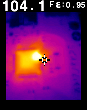
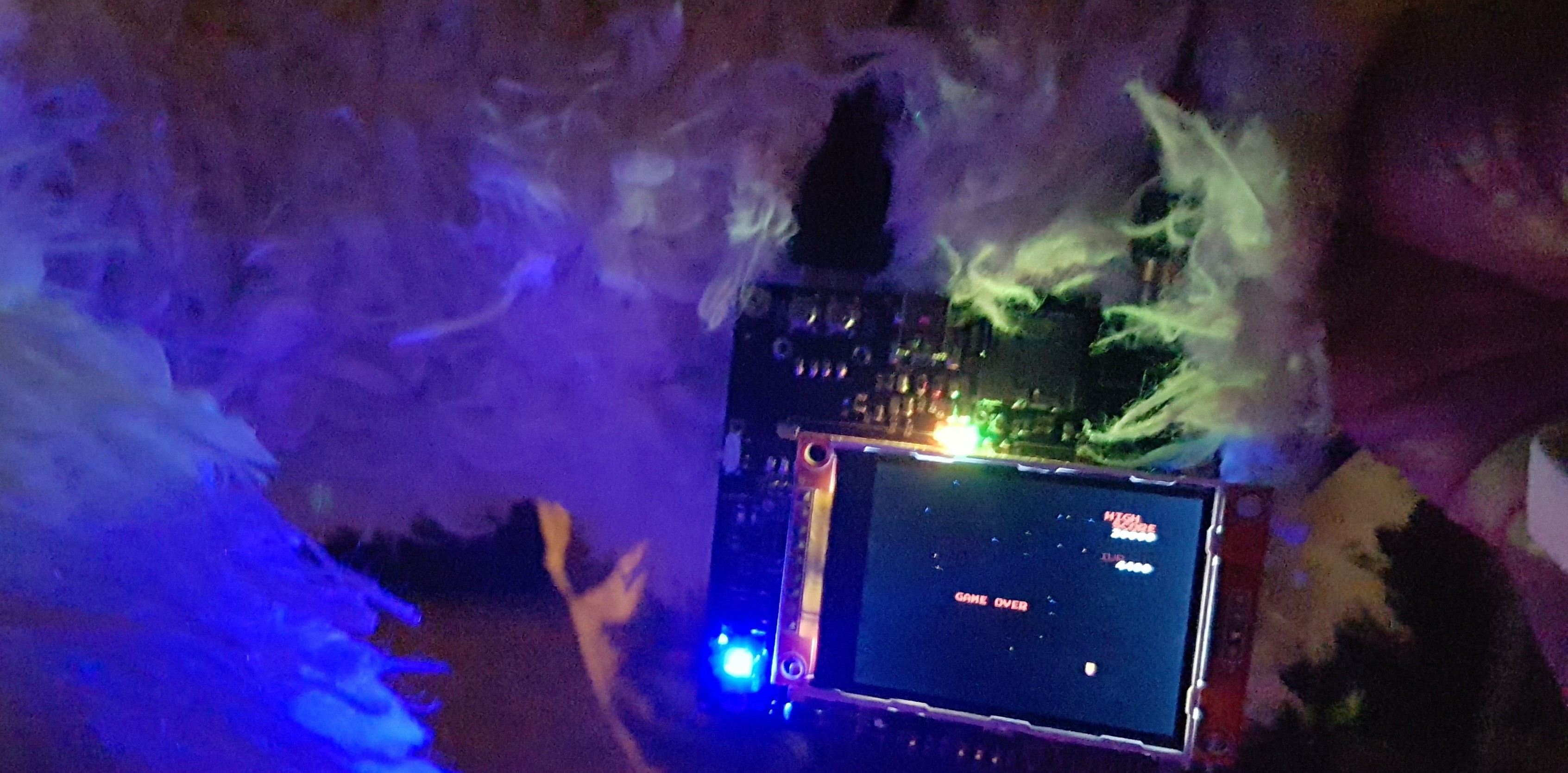
It is admittedly very hard to see this but there is smoke coming out of this CPU from last weeks adventures in rewiring boards with kynar wires and what not.
Toasty
I have to laugh that as i am editing this, the above video at the end shows the YouTube recommended next video on this frame

The replacements were were built yesterday and one of the boards is using a STM32F405/415 CPU, which meant a small schematic change to move VCAP1 and add VCAP2, also a part change to 2.2uF for the caps instead of one 4.7uF which to be honest, we cheated and put two 4.7uF's since I didn't feel like wading through our boxes of gear to find an 0805 2.2uF and none of my kits go up that far.
The difference between the 405 and 415 is that the 415 has hardware crypto, so we installed the 415 which means likely export restricted prototype! The reason for the looking at the 4x5 chip is because it has 1024K flash and 192K RAM which is nice.
mmca built both the prototypes, flashed it and it didn't go beyond the RED screen mode, which means it can't find USB controller, sheesh not this again.. but reasonably quickly I realised I had the test mode projected load ed up which only did USB device, HID host and make the screen RED, so flashed the EMU project and it kicked into life. Not before a couple of lets check some connections, but before we wrecked the boards. Pro Tip don't use the same colour for error waiting for USB on one project, and everything is groovy man on the other project, in fact even use text since its a screen not an LED !
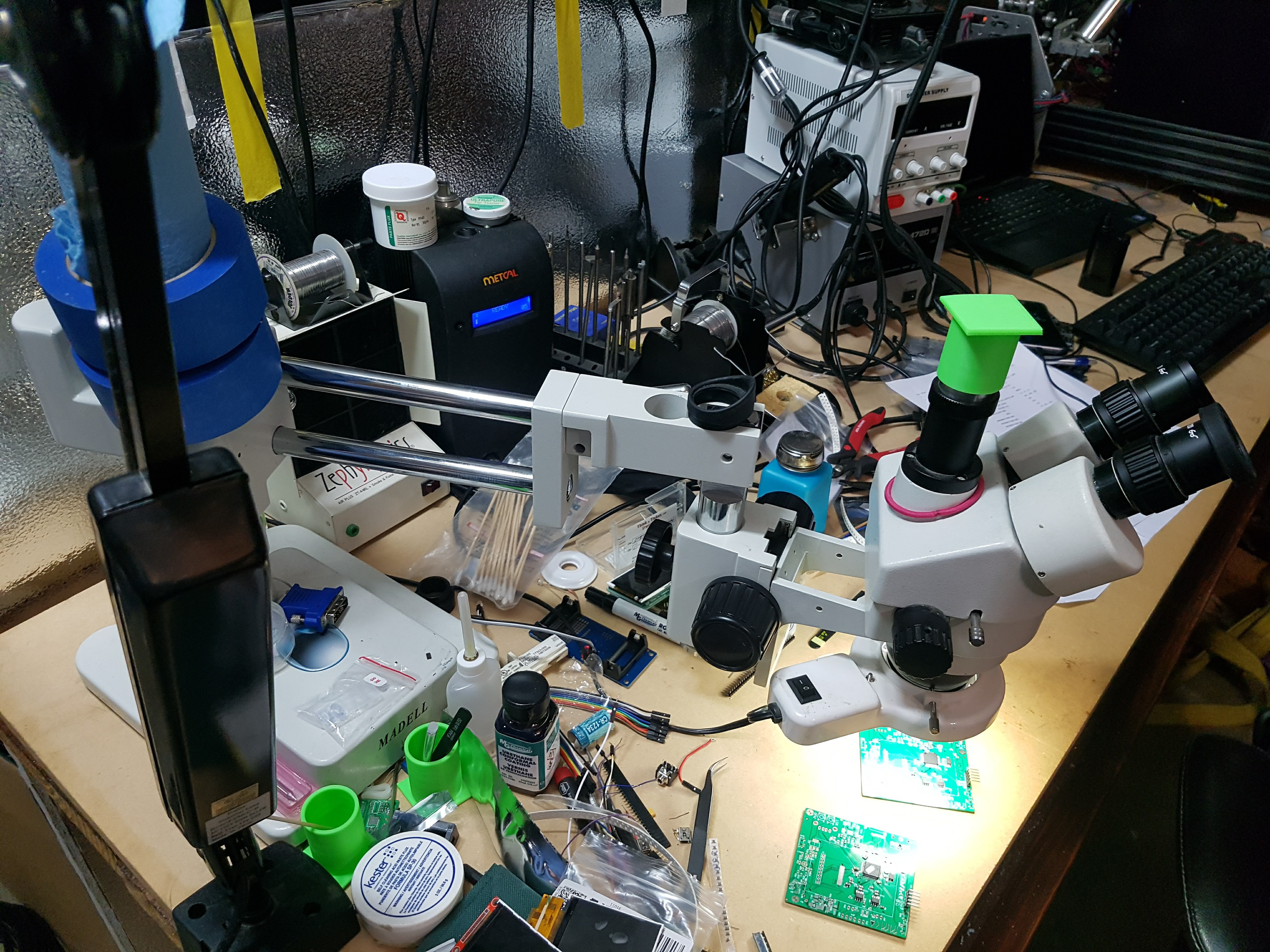
Latest revision being built by mmca
The second board with the 415 booted up OK but this time it also got stuck at the USB mode, but it is a different chip so likely its just a firmware issue, I threw together a quick CDC test in STM32Cube and proved out at least that the USB device works. Which brings me to the next part, which I'm glad i figured out a while ago, because it was a tricky one.
So I'm noting this in here, possibly again, since i always forget where it is, but in STM32Cube CDC_DATA_HS_MAX_PACKET_SIZE is defined as 512, which won't work in windows (maybe elsewhere) at least, so set it to 256. You'll see the device enumerate but it will have a yellow exclamation mark. It is defined in usb_cdc.h
take out bad
/* CDC Endpoints parameters: you can fine tune these values depending on the needed baudrates and performance. */
#define CDC_DATA_HS_MAX_PACKET_SIZE                 512 /* Endpoint IN & OUT Packet size */
#define CDC_DATA_FS_MAX_PACKET_SIZE                 64  /* Endpoint IN & OUT Packet size */
#define CDC_CMD_PACKET_SIZE                         8  /* Control Endpoint Packet size */
put in good
/* CDC Endpoints parameters: you can fine tune these values depending on the needed baudrates and performance. */
#define CDC_DATA_HS_MAX_PACKET_SIZE                 256  /* Endpoint IN & OUT Packet size */
#define CDC_DATA_FS_MAX_PACKET_SIZE                 64  /* Endpoint IN & OUT Packet size */
#define CDC_CMD_PACKET_SIZE                         8  /* Control Endpoint Packet size */
I did that, reflashed and uploaded back to the board (noting i'd left the 3.3V power on the stlink) and our CDC device appeared. I'll do a walk thru video of it in STM32Cube which is super easy for these tests.
As I am writing this , also back and forth emailing with Laen from oshpark about a special run of boards we want to do, he just emailed me and is breaking my heart on the idea we had for the boards :) but as always he's great and super nice to deal with, I'd really set my sights on this board design too, it requires another factory to do the work and a special run, because it is a more or less discontinued process.
At the moment i'm doing a second battery test, since the first was a run-time test with the DMM logging the output of the 5V from the boost circuit, so now i am measuring the battery.
UltraFire it cracks me up.
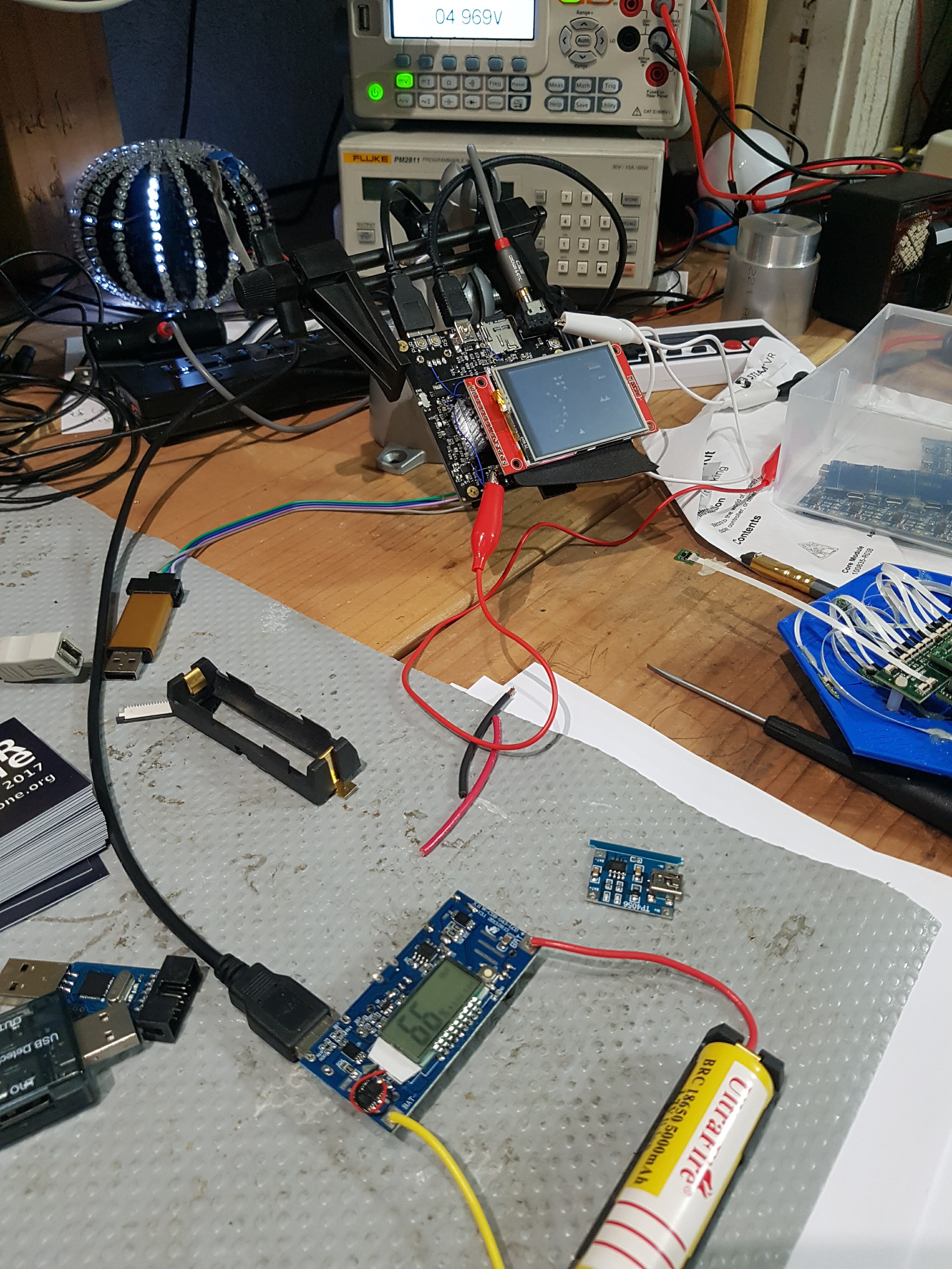
The battery is connected to the innards of a 4 cell 18650 cell phone battery back, which you know was one of those late night eBay shopping for PCB's (when will i ever use this ) which then in turn feeds the badge which has kynar wires to skip the on-board buck/boost/battery setup. So the results from that were really good
The key parts are noted here, so it ran from 20:52 to 08:08 the next day, that is a lot better than I expected, we figured extrapolating from the 800mAh test it'd be about 7 hours, 5000mAh ? seems unlikely. Our stock of 800mAh batteries have been on the shelf for a few years, but either way it wasn't going to be enough time.
---== Log File Started 2017-02-18 20:52:
2017-02-18 20:53:08) 5.076265V
2017-02-18 20:53:38) 5.076093V
a smallish drop
2017-02-19 01:29:51) 5.087614V
2017-02-19 01:30:21) 4.969240V
2017-02-19 08:08:03) 4.984530V
2017-02-19 08:08:34) 0.528674V
In 11 hours or so i should have a new graph of the voltage measurement at the battery, i need another logging DMM now...Also remind myself to change the format of the log file to a more CSV'ish like so i can import it directly, option buttons in GUI pls.
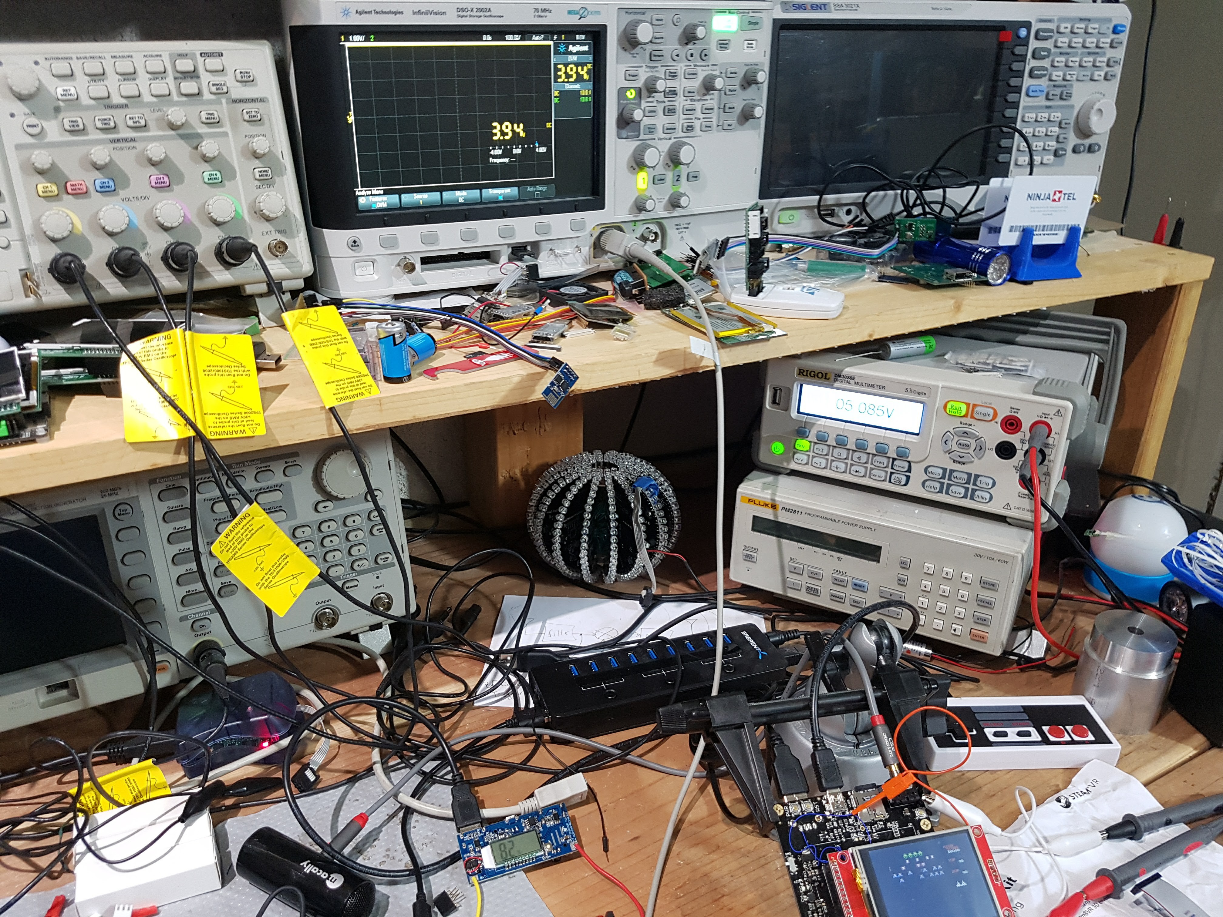
Since my other desktop DMM is at NSL, i used the scopes DMM feature to monitor the battery though i haven't written a logger for that yet. Plus I didn't want to leave it on all night, 3.94V after approximately an hour not bad at all. The 82% on the buck/boost might be accurate too.
Update 22:50 2/19/2017
The second battery test just finished, here is a graph of it
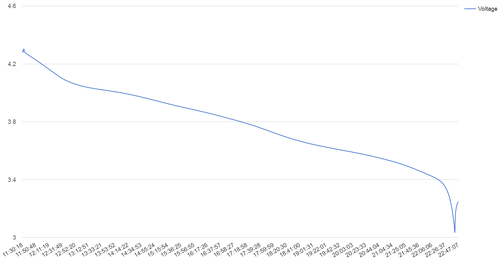
Started at
| 2/19/2017 | 11:30:18 | 4.288567V |
Ended at
| 2/19/2017 | 22:41:37 | 3.056V |
Not bad and similar time to the first test. That last bounce back is when the USB buck/boost switched off due to the battery reaching too low a level, the battery bounced back to about 3.28V, it might go more the buck/boost has some smarts for the % left, but it is not calibrated for 1 cell though it will try to match it. And it does switch off when it thinks it is at 0%. But a solid run-time and rechargeable and anything left is probably in the minutes range, as you can see by the drop off at the end.
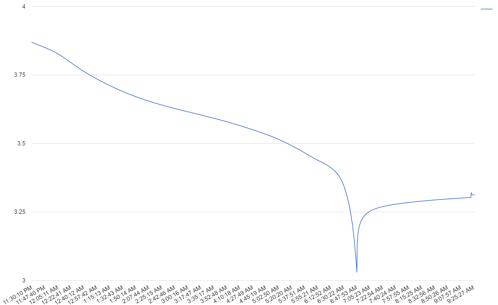
Another overnight test but the battery wasn't fully charged the charger that comes with it charges at a very low rate, so takes forever. I should switch out to the smart charger. The sharp drop/recover is where the boost converter switches off. But the profile is staying the same, now i'm testing with the yellow UltraFire.
As a tangent, I remembered that I had added support for the Wolfram Alpha cloud data drop in my DMM app, and totally forgot about it so my DMM has been logging to the cloud for a few days. I had planned to push it directly to Google sheets, but apparently they are flakey and will turn off API access occasionally for scripts and you have to re-auth it, which isn't much good for a data logger that can be long term, so I came across the Wolfram solution. The free drops last a month or so. I looked at a few other IOT .io services as well.
Super easy to add, dataBin is the ID of the data drop which you get from them, value and unit type is what i logged.
HRESULT CRMDlg::LogEntry ( const double value, CString unit )
{
    HRESULT hr;
    CComPtr<IXMLHTTPRequest> request;
    CString url;

            //  Build custom URL
            url.Format ( _T ( "https://datadrop.wolframcloud.com/api/v1.0/Add?bin=%s&key1=%g&key2=\"%s\"" ), dataBin, value, unit );

            hr = request.CoCreateInstance ( CLSID_XMLHTTP60 );

            // sent the GET request
            hr = request->open (
                     _bstr_t ( "GET" ),
                     _bstr_t ( url ),
                     _variant_t ( VARIANT_FALSE ),
                     _variant_t(),
                     _variant_t() );

            hr = request->send ( _variant_t() );

            // get the status of the request
            hr = request->get_status ( &status );


    return hr;
}
We're dropping the buck/boost off the main board and doing something we've always talked about doing, so see how that goes. I also changed the 5 Pin connector for the ST Link V2 to the same 10 pin layout as these ST Link V2 clones we have a box of to include with the badge.
The LCD source continues to be a pain , mcufriend just won't reply to me, they removed their store from aliexpress and taobao and made their own hosted one, but they only ship locally and won't answer emails.. So back to the 2.2" ILI9341 we've been using since the early days, not as a module but a bare LCD to go to the FPC pins on the board (reminder that i have to lengthen the copper pads to allow us to move the FPC back and forth for the 2.2", 2.4" and 2.8" variants.)
I also just found a 3.2" variant that is SPI for about 54 YUAN (around $8) that has claimed stocks of 2000+, that same display on the usual suspects goes for around 20$-40$ USD , it has a touchscreen too.
Today I am going to layout the new board in the final shape, change the CPU driven transistor to LCD backlight arrangement from sink to source and run it off the 5V line, then route the board and send it out for manufacturing then I have to leave for Mobile World Congress in Spain where I hope to meet up with ST Micro, I missed them at CES, and put my pls sir hat on, then off to the UK, and hopefully when I am back the boards will be here ,about two weeks from now...not a great time to lose so much time for this project. But have to pay the bills somehow.
Paper rough cut out of the new shape (but hidden) and the display for test fit, mmca likes the larger badges, i liked the smaller badge we did last year, the mars bar as i call it. Or we do a giant one.

I hope I re-read all these notes. Also for my somewhat continued sanity let me remember not to use, and if i do to check that i did not do ra ! gnd in eagle and forgot about it before I ran the CAM process. Though we're building up a nice pile of not so much prototype boards for an art project.
Then we'll build the final prototype. Or maybe i'll got nuts again and get that 3.0" RPI screen in, which I can't buy anywhere, the number of the back of the LCD doesn't show up in google or bing, and we have no driver for it.
Also wish me luck for having 450 random 18650s stored in my house for a few months.
Til next log
Discussions
Become a Hackaday.io Member
Create an account to leave a comment. Already have an account? Log In.