 Tobias Blum
I had this RGB LED matrix lying around for a while. I used it with a arduino mega (works good but no easy internet connection) and raspberry pi (flexible, but a big overhead and long startup time). So I was looking for a better solution and I found it when I saw this article on hackaday: https://hackaday.com/2017/11/28/a-minimalist-weather-clock-with-a-unique-display/
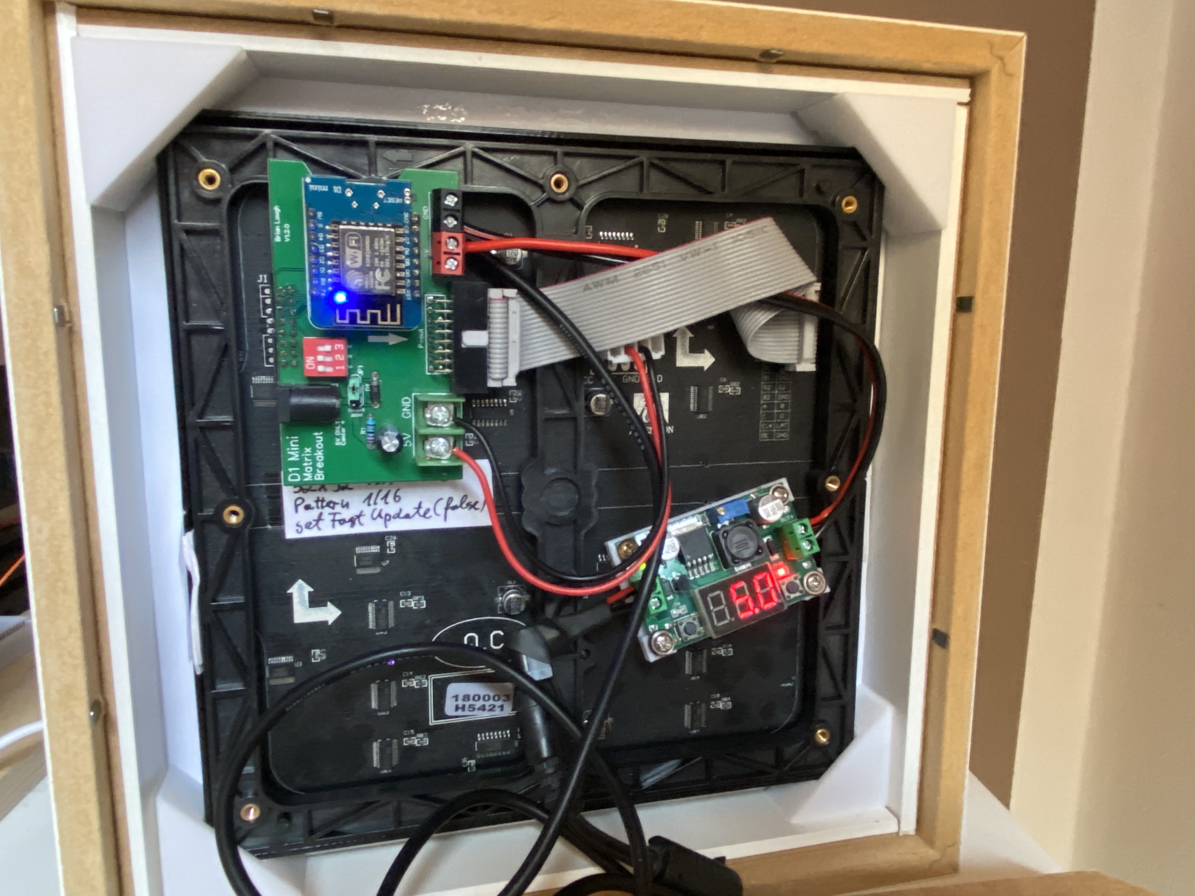
Dominic Buchstaller built a neat library for the ESP8266 to drive these RGB LEDs matrices. So connecting to the internet for NTP sync is no problem anymore. It also boots up instantly and can be powered off without shutting the system down before.
I had the idea to build a NTP synced clock and was looking for a creative way to display the time using available colors. After some googling I found a monocrome version of the tetris clock in some china shops. So I decided to build something similar using colors.


 Benchoff
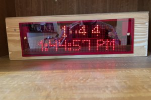

 saarbastler
 Chris Carter