 lion mclionhead
Grid fin closeups:
https://www.teslarati.com/spacex-used-falcon-heavy-booster-photo-gallery/
https://twitter.com/elonmusk/status/879065552060260352
The BFR grid fins are expected to be the same as the Falcon 9 grid fins.
Developing grid fins exposed more limitations of Freecad & just how complicated grid fins are. They're right against the camera & the most iconic SpaceX assets, so they need a bit more detail than the engines. Still left out the fillets & cutouts, to save on polygons & allow for future changes.
Could only imagine how focused the employee was who designed them & they were designed by 1 guy in only a few months between the 1st landings in mid 2016 & their fabrication in early 2017. Being an iterative design with a tight deadline, they were probably modeled by hand & mirrored. They might have had some guide curves & drawn all the saw blades by manually inserting arcs. The limitations of freecad's interface made scripting more attractive.
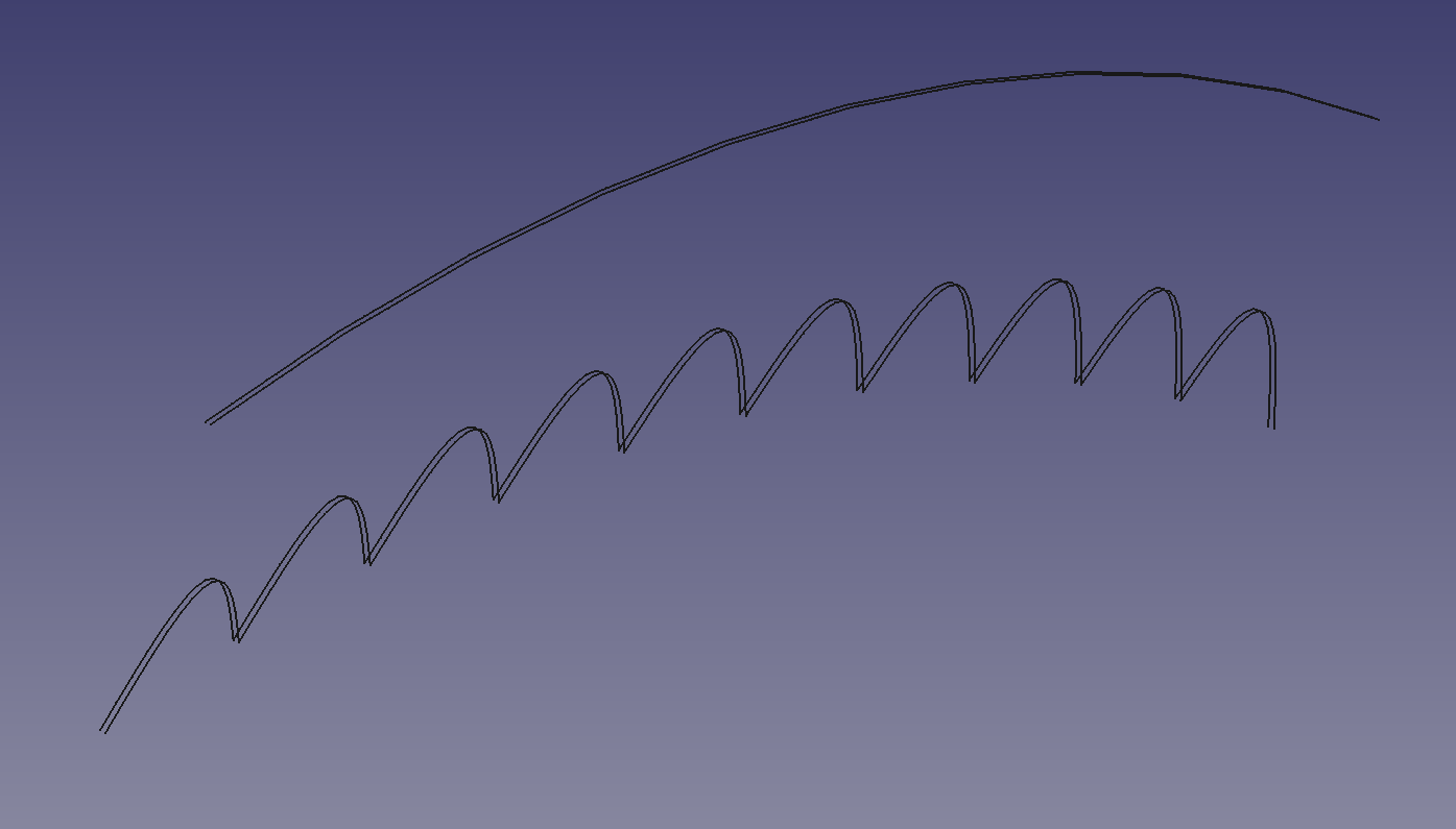
Traditionally, you loft between 2 faces to get a solid sheet of metal, but those sawblades have many points & Freecad can't loft 2 diagonal faces with many points. If you try making the faces on an axis & then rotating, the problem is many other curves which are not perpendicular to the saw blade.
The easiest route was lofting down a tube of rectangles.

The freecad loft of course is limited to 16 rectangles at a time.

The result was beautiful saw blades made of solids, which could handle booleans but were too slow to do anything with. Conceded Freecad couldn't make solids this complex & lofted a tube around 4 lines instead. Lofting appears to be the only Freecad script which works.
120 curves made the grid pattern. Since Freecad has no recursive selection feature, starting over the automated section while keeping paw drawn sections around was a time consuming process.
The mane challenge was those grid fins aren't flush on the fuselage, but rise away from the hinge to give leverage without adding mass. Without solids or any deform feature in Freecad, the easiest route was implementing bezier curves in python.
The hardest part was the complicated hinge mechanism. It would be easiest by drawing manually, but after adding just 2 sweeps & a boolean to the automated grid section, Freecad could no longer load the file. The load operation only locked up the keyboard & crashed.
The struggle with freecad made this
https://imgur.com/gallery/s2gAx#SkPcbiZ
look all the more impressive. To be sure, it was done with a much better program, but 3D modeling is complicated enough to be like a career. Even with photogrammetry looking slightly better than 20 years ago, it's still awful & photogrammetry still can't move ideas from the brain to the computer.
Discussions
Become a Hackaday.io Member
Create an account to leave a comment. Already have an account? Log In.