 Beaglebreath
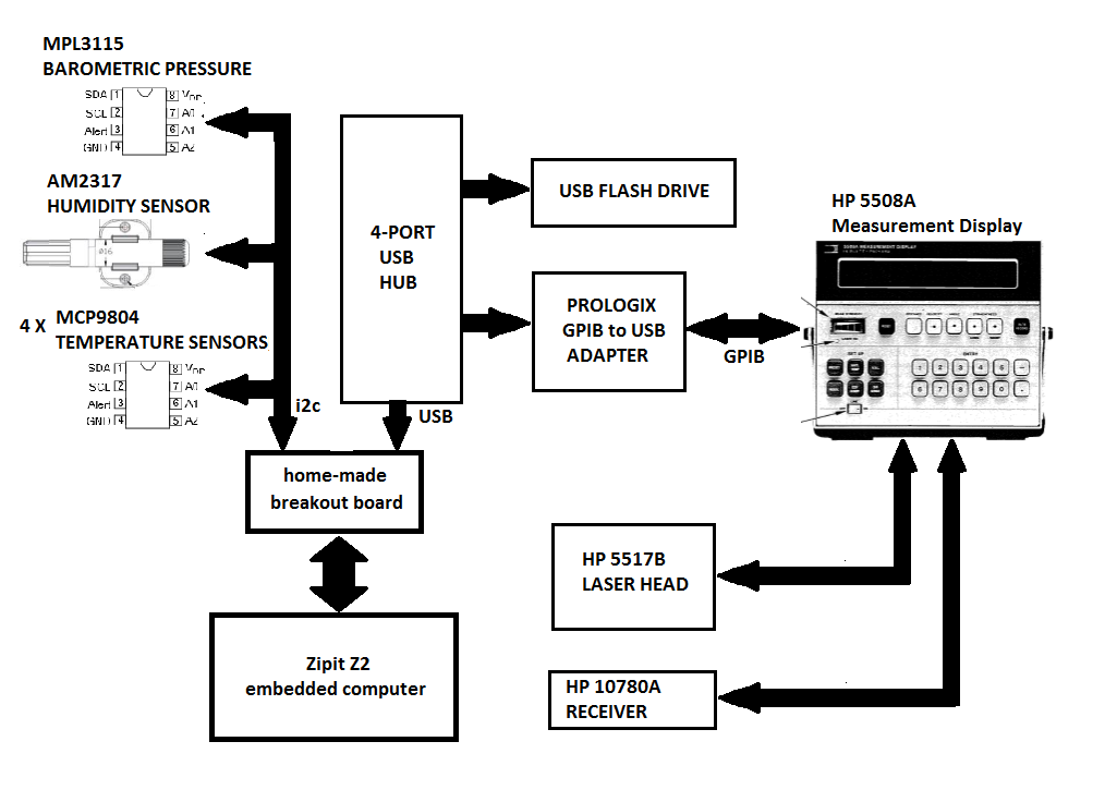
I learned about the Michaelson Morley Experiment about 20 years ago in college. At that time we also built a Michaelson interferometer on an optical breadboard. I was amazed at the sensitivity of the interferometer. Even with the optics levitated on pneumatic isolation legs on the optical bench, we could easily see people's foot-falls from the hall way outside of the lab and we could see vibrations caused by trucks driving down the road outside. A few years ago I read an article about commercially made interferometers. I became enamored the HP5528A laser interferometer manufactured by Hewlett Packard in the 1970's. I became interested in building a linear measuring machine which would be capable of making calibrated length measurements
0%
0%
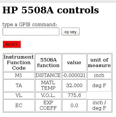
repurposed luminiferous aether detector
over the last few years, i've build up a functional laser interferometer. now i want to use it to accurately measure distance.
Become a Hackaday.io member
Already have an account? Log in.
Just one more thing
To make the experience fit your profile, pick a username and tell us what interests you.
Pick an awesome username
hackaday.io/
Your profile's URL: hackaday.io/username. Max 25 alphanumeric characters.
Pick a few interests
Projects that share your interests
People that share your interests


 Lithium ION
 Leonardo Gomes
 Juan Albanell