 Skyler Brandt
This week I worked out a few more of the bugs with the reflow oven and solder paste dispenser, build a box for the Raspberry Pi and touchscreen, and assembled the power control board.
After watching a few videos of other people's reflow ovens, I noticed that they had a thermal mass connected to the end of the thermocouple. Mine was only floating in free air so that would have thrown off the readings because it doesn't accurately show what the temperature of the part I would be trying to reflow. To implement a thermal mass, I simply stuck the end of the thermocouple though a hole on a protoboard.
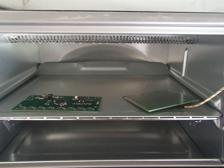
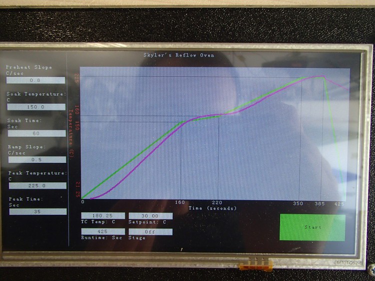
This also fixed the problem of the ugly wire to keep the thermocouple suspended in air. However, the thermal mass complete throw off my PID tuning, so I had to redo that. It went a lot smoother the second time around, and I'm much happier with the results.
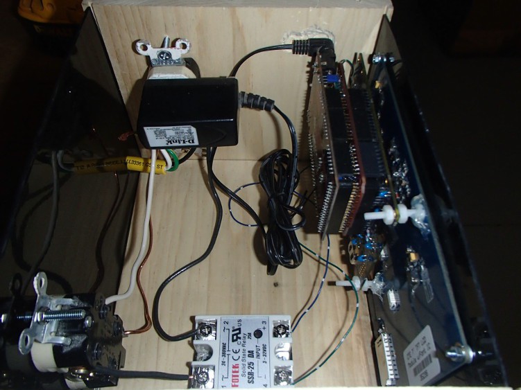
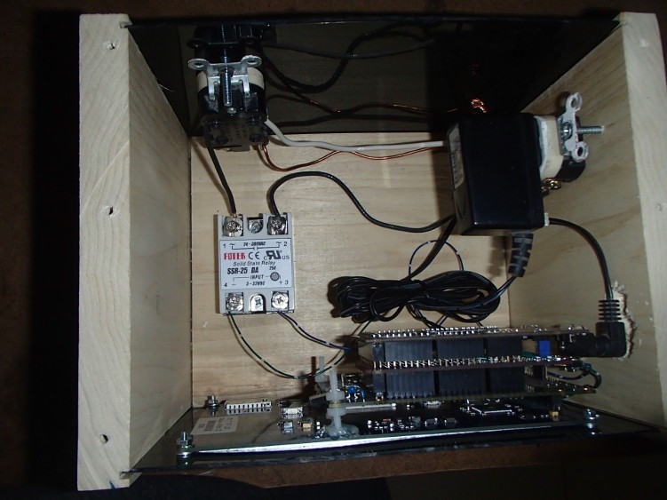
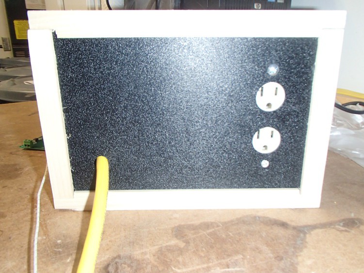
 As promised in my last post here are the pictures of the inside (and back) of the reflow oven.
 I also figured out my issue with my solder paste dispenser. The paste I ordered was a little dried out. Sparkfun has a video about revitalizing solder paste and its simply stirring in flux until the consistency looks right. That made all the difference in the world though. I was able to use the really small, 26ga, needles and work with the small pitch parts, ie TQFP, with ease.
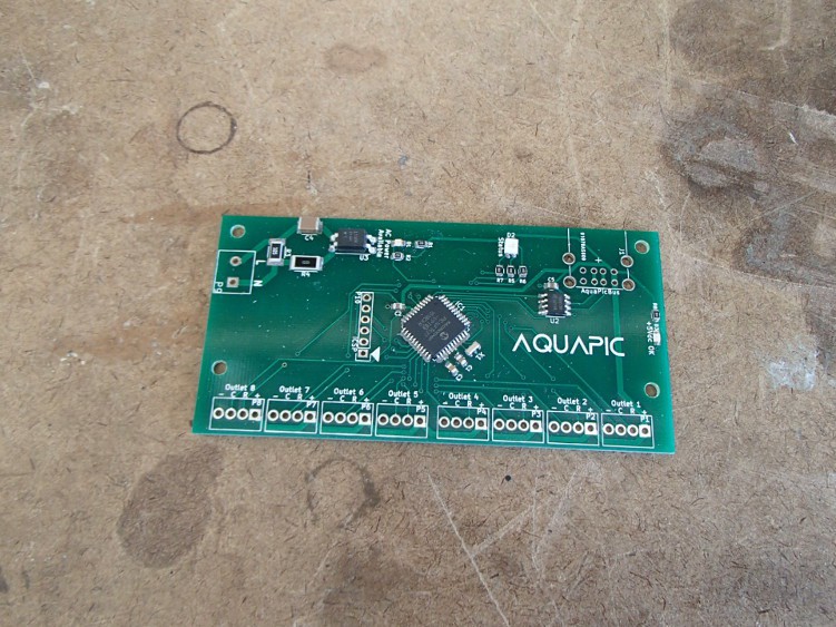
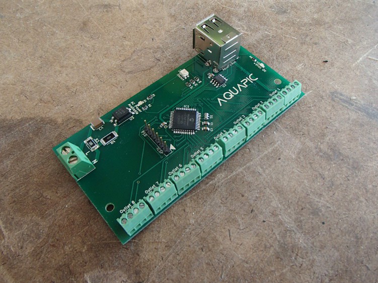
The above picture is a power control board ready to be reflowed, and below are the finished product. I haven't had time to program and test the board to make sure everything works. Fingers crossed.

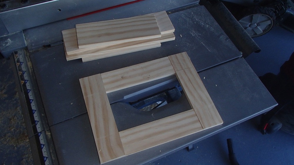
Finally, I built an enclosure/box for the Raspberry Pi and touchscreen. Its made out of pine ripped down to ~1.75" by 3/8". The front is joined by simple rabbet joints and the sides are straight glued.
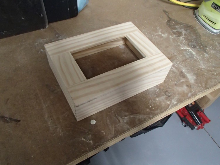
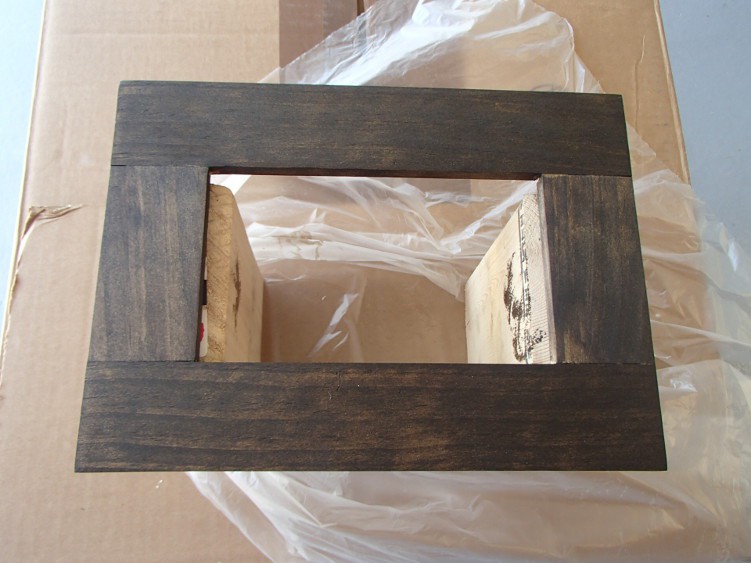
I've strained everything a nice dark finish, but haven't applied a clear coat yet.
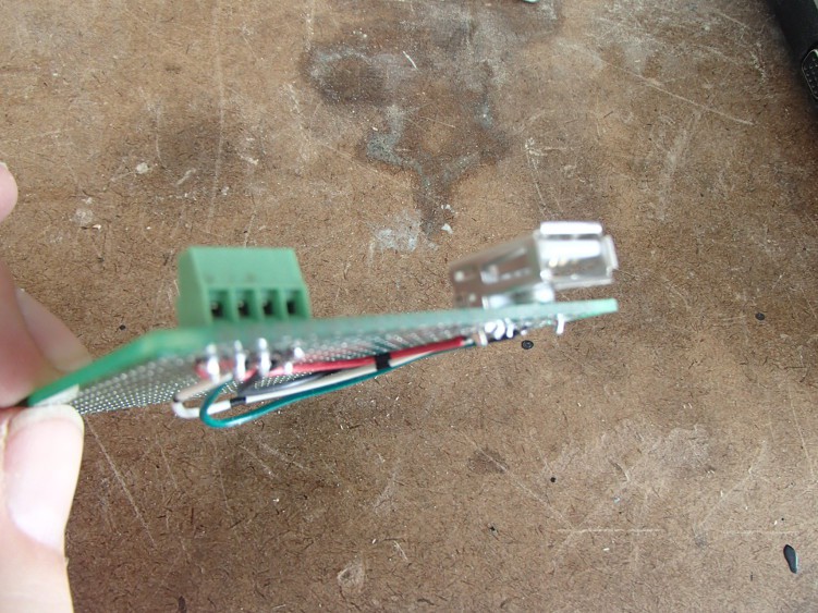
I made a "breakout" board for the communication, AquaPic Bus, and power. The AquaPic Bus is a RS485 protocol I wrote. I'm using a USB to RS485 dongle on the RPi, because it was a lot easier than using the UART pins on the GPIO and then having to level shift from RPi's 3.3V to 5V.
I then attached the "breakout" board and the RPi to the enclosure backing, and did a little wiring. I'm going to make a short jumper cable between the power on the screw connector with a micro USB connector on the other end to power up the RPi. The 5V for this will come from the same power supply as the rest of the cards.
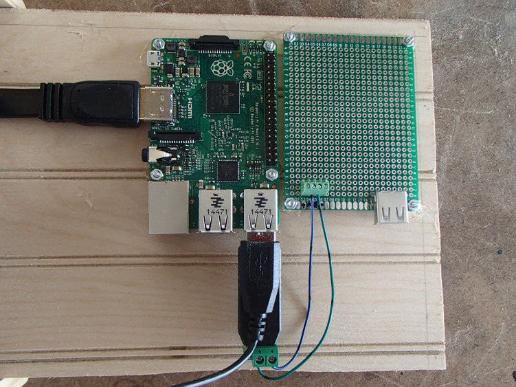
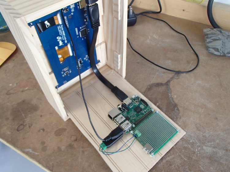
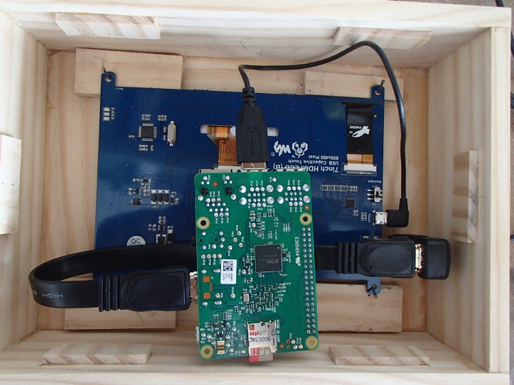
This is the inside of the box and how the RPi will be positioned when the back is in place.
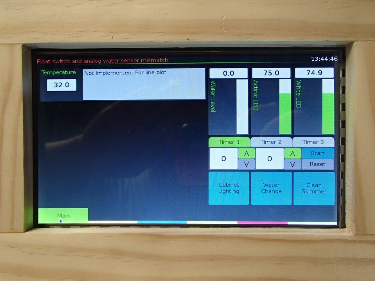
Before I starting staining the box I had to power up everything and make sure it worked.
Discussions
Become a Hackaday.io Member
Create an account to leave a comment. Already have an account? Log In.