 Skyler Brandt
I'm 95% done with my first prototype. Everything is assembled, and mostly working. I had quite a few issues and bugs to get to this point though. As I highlighted in my post two days ago, my RS485 protocol didn't work on the Raspberry Pi because mark and space parity isn't implemented under the Mono frame work. I took the easy way out and simply counting the number of high bits in the byte. Then I set the parity to either odd or even to get the desired 9th bit.
The next issue was all because I sometimes buy cheap "quality" Chinese parts. The original power supply I ordered to power the controller didn't work like I wanted it to. It was a dual supply, +5Vdc and +12Vdc, but for some reason I couldn't tie the commons together. I didn't look into, or care why, and instead ordered two separate power supplies. Another nail in the coffin of the original power supply was the switching frequency. It's in audible range, probably around 10ish KHz, and extremely annoying.
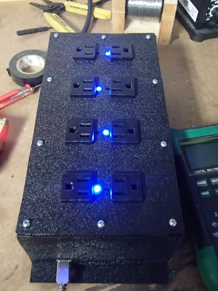
The power strip went together fairly easy. I don't really like the case but it works. Its made out of ABS plastic sheets. I cut all the pieces out, then bent over tabs on the edges to make a surface to glue everything together.
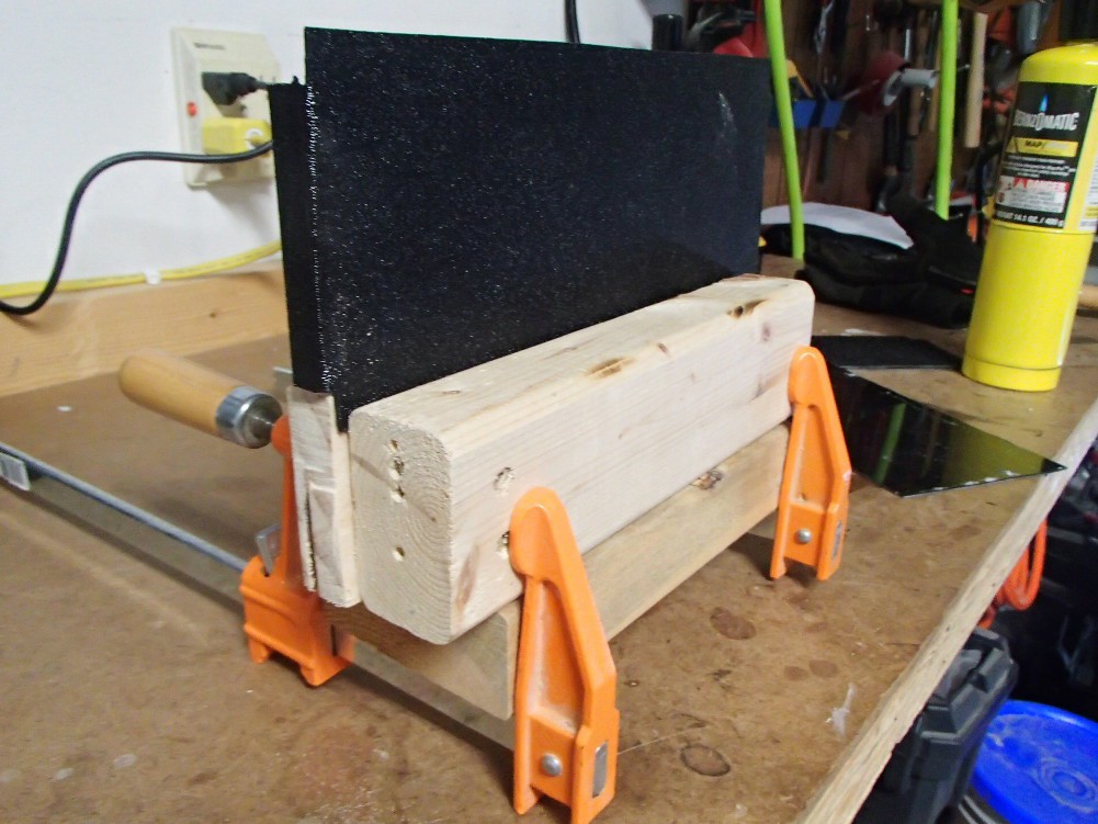
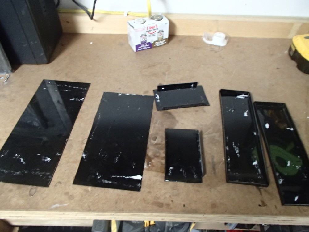
I then used pipe cement to glue everything together. The top and bottom are held on by 6-32 machine screws. I threaded the plastic so I didn't have to use any nuts. It's definitely not elegant, but I don't cool machines to do anything prettier, like a CNC machine or a lazer cutter. And no, a home hobby 3D printer is not cool.

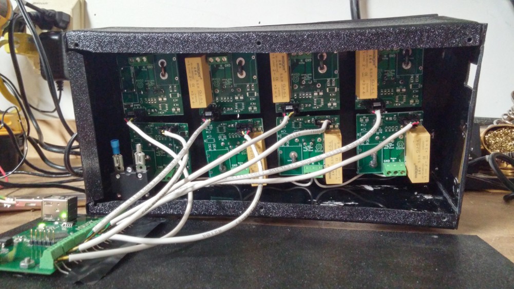
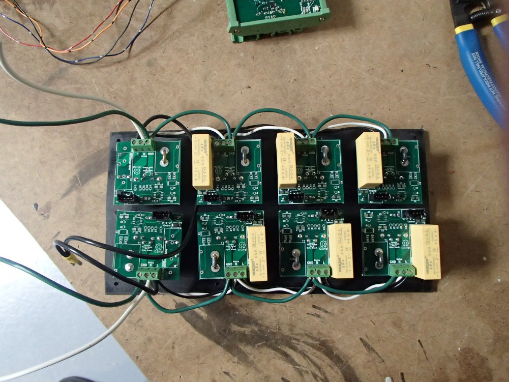
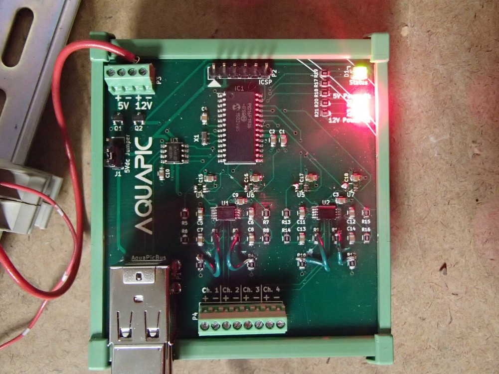
Before I wired all the outlets up to mains, I wired up the control circuity and tested that. I had to parallel 10K resisters between the relay control and ground pins of every relay board, because I left the gate of the MOSFET floating. The terminal strips are really close together so I layered the resisters between pieces of electrical tape to keep anything from shorting together. Added bonus though, it looks even more cobbled together.
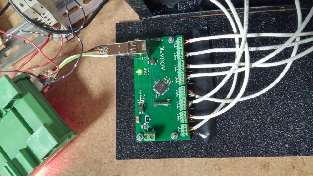
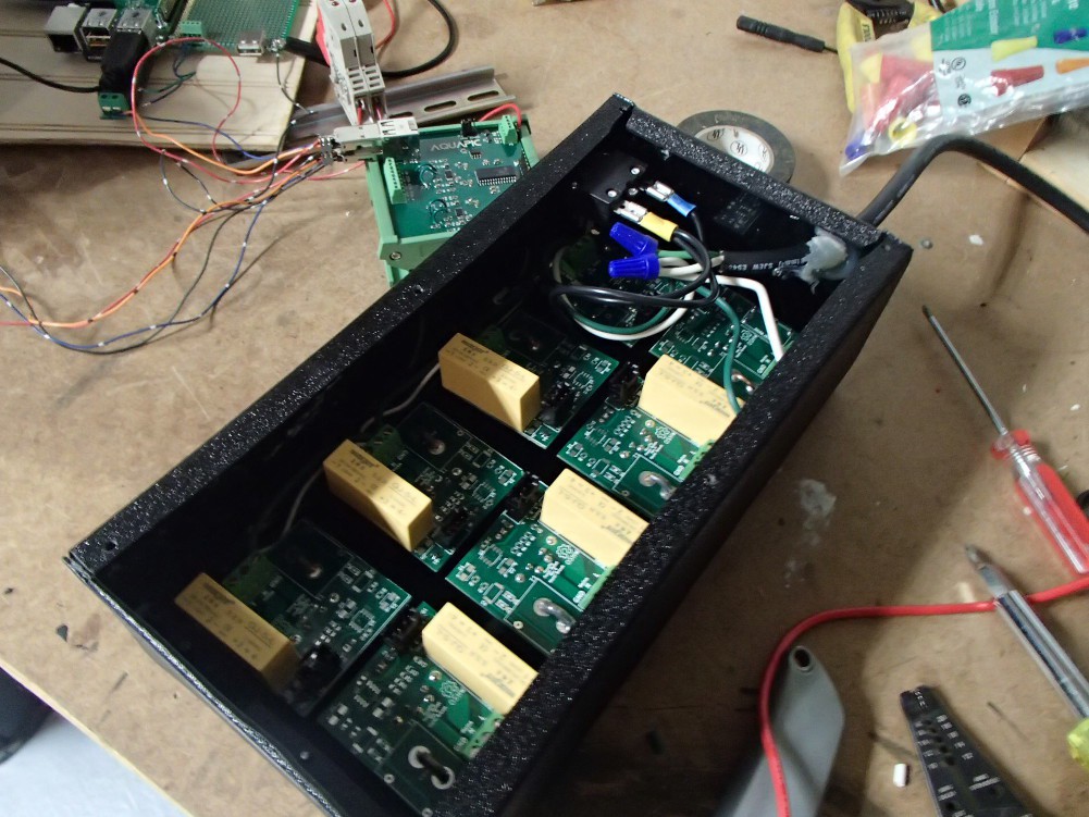
The last bit of progress was that I added a WiFi dongle to the RPi. I thought I would have to write a little script to get the time from a NTP server on boot, but the RPi automatically does this when it has internet. That was a nice surprise. Now the only thing holding me back from implementing this on my tank is some communication cable. I'm using regular USB cable but it is ridiculously hard to find plain USB cable without ends. So I ordered long pre-made USB cables and I'm going to chop them up into the lengths I need. I also need to clean up the inside of my tank cabinet so I have a nice place mount everything and make it pretty.
Discussions
Become a Hackaday.io Member
Create an account to leave a comment. Already have an account? Log In.