 Skyler Brandt
I've been continuing the trend of cleaning up the project by moving all the board designs and firmware into a single repository. The first reason for this is that the board designs are now revision controlled with git instead of copying directories. The second is that hopefully this reduces the confusion between what firmware is meant to run on which board revision.
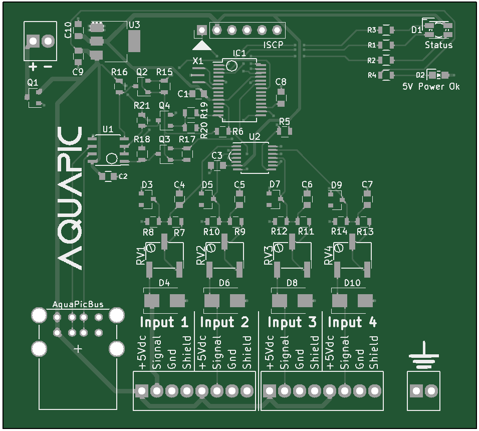
I also started replacing all the PIC16F microcontrollers with PIC32MM micros. So far the only card/module that is using a PIC32MM is the analog input card. The new PIC32MMs are about the same price as the older PIC16Fs but with a lot more power. More power probably isn't necessary but the analog input card performs quite of bit of 32 bit math include multiplication and division. The PIC16Fs sport an ALU that doesn't include any hardware multiplication and are kind of terrible at even 8 bit multiplication. The PIC32MMs shouldn't have any issue since the architecture has a single cycle multiplication unit. I briefly thought about using an ARM Cortex-M, but ARM is an entirely different ballgame than I'm used to.
While redesigning the analog input card I decided to go with a dedicated ADC with 16 bit signed resolution. All of the analog temperature sensors I've looked at have a rather small resolution, i.e. voltage per degree C, so I decided that 16 bits was the easiest solution to overcome the small resolution and avoid implementing some sort of amplifier circuity. I also added protection on each of the inputs. Its pretty standard input protection with the exception of the potentiometer. The pot is used to vary the value of voltage divider and thus vary the input voltage to the ADC. This allows for increasing the ADC input voltage for devices that have a limited output. For example, the MCP9701 outputs a voltage around 2.8Vdc at 125°C. With the pot bypassed the ADC input voltage will be 1.89Vdc. Fairly close to its full scale voltage of 2.048Vdc. However, the pressure sensor I'm using to measure level will output almost 5Vdc at full scale. In this instance the pot can be used to add resistance to limit the voltage such that it doesn't go about 2.048Vdc but also maintain an ADC input voltage of 2.048Vdc at the sensor's full scale output.
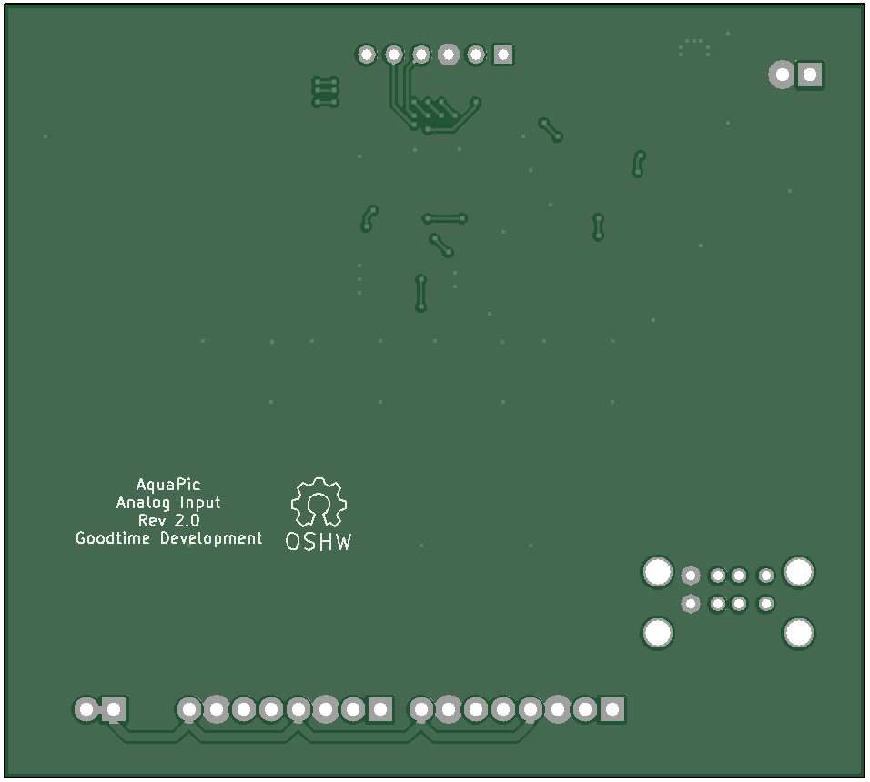
As always here are the board renders of the newly designed analog input card:
Discussions
Become a Hackaday.io Member
Create an account to leave a comment. Already have an account? Log In.