 Curt White
If I couldn't add additional sensors to the X9 Activity Tracker it would be useless to me. To be perfectly honest, I don't even particularly like activity trackers. Unlike an Arduino, Teensy, ESP32 or ARM Cortex breakout board, hacked activity trackers don't provide convenient access to additional MCU GPIO for adding sensors etc. There is a simple solution: cannibalize GPIO from existing components. I always remove the OLED for my own projects. I'd rather interact with devices using a mobile app or web application over Bluetooth. Bluetooth is the whole reason I find Nordic chips so appealing. Take a look at the below example of how I desolder the X9's OLED display to gain additional GPIO for sensors:
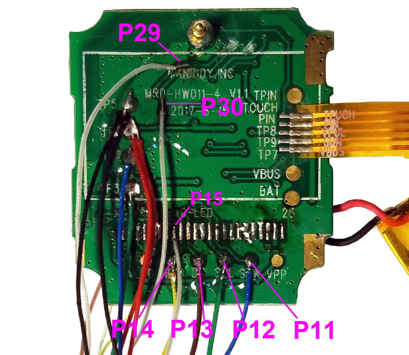
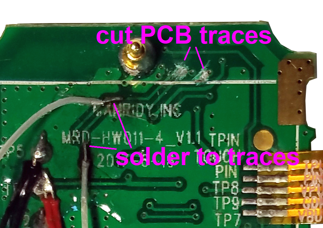
The primary OLED GPIO (P14, P13, P12, P11) are really easy to access because there are nice big test pads to solder underneath the OLED ribbon cable. P15 is a little bit harder because you have to solder the place where the ribbon connected, but still no biggy. But what if you need more GPIO or want to keep the OLED? You can access P29 (heart rate detector photosensor) and P30 (touch sensor) by scraping off the solder mask from the appropriate traces and directly soldering a wire to the trace. You will want to isolate your connection to the MCU from supporting circuitry related to the original use of those GPIO. In order to do this, solder to the trace in a place where there is nothing connected between your solder point and the MCU (nRF52832), then cut the trace above your solder point.
You can use this annotated, highly detailed composite microscope image of the X9 PCB (high resolution version in project files) and list of component pin connections to figure out traces you might want to solder into:

- HR_LED_PIN 4
- HR_DETECTOR 29
- TOUCH_BUTTON 30
- VIBRATE_PIN 8
- BATTERY_PIN 28
- OLED_CS 15
- OLED_RES 14
- OLED_DC 13
- OLED_SCL 12
- OLED_SDA 11
- OLED_LED_POW 16
- OLED_IC_POW 17
- KX126_CS 24
- KX126_SDI 19
- KX126_SDO 20
- KX126_SCL 18
- KX126_INT 23
- FLASH_CS 22
- FLASH_SDI 19
- FLASH_SDO 20
- FLASH_SCL 18
Discussions
Become a Hackaday.io Member
Create an account to leave a comment. Already have an account? Log In.