 Yann Guidon / YGDES
Construction of one bit of the register set is looking good. I made several adjustments to the original design:
- A separate power supply for the latches and the output.
First reason is to prevent current spikes (during switching) to affect the stored value. A series resistor and a capacitor reduce the susceptibility to electric intererence.
Second reason is that I may want to drive the output with a higher voltage to increase the fanout.
It makes the overall design a bit more complex but a bit safer too. - I use old green LEDs to show the state of one latch. Each draws only 20mA instead of 50mA for the Glühbirnchen. This again increases fanout.
- Added series resistors for the latch inputs.
- Each relay has their own driving pin. Yes, that's a LOT of signals to drive and wire. However it should reduce the overall power consumption because only the required relay is energised. There are 21 MUX2 for the register set read and write, and at most 9 will be energised instead of 2.5× more. Of course it increases the complexity of the driving logic but it's already covered in a previous log.
- The input of two of the latches is directly accessed so the register value can be overdriven by external circuits, in particular for memory read (during the latch cycle, to prevent conflicts with the writeback cycle).
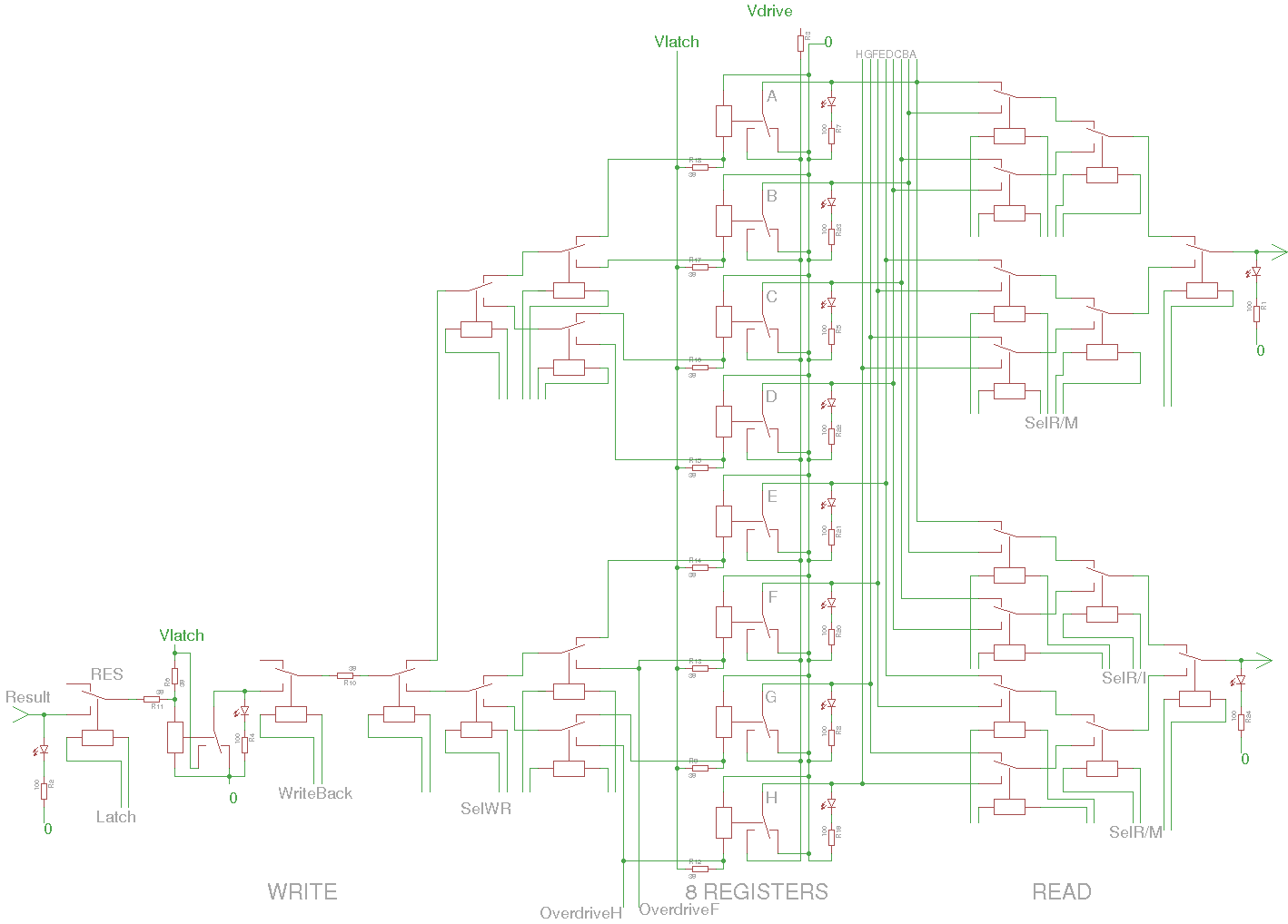
For each bitslice module, I have selected a 2×40 pins header. Most of these pins are used for the MUX. There should be enough pins left for the ALU.
And here you can see 32 relays in all their glory, taking one half of a 160×100mm protoboard:
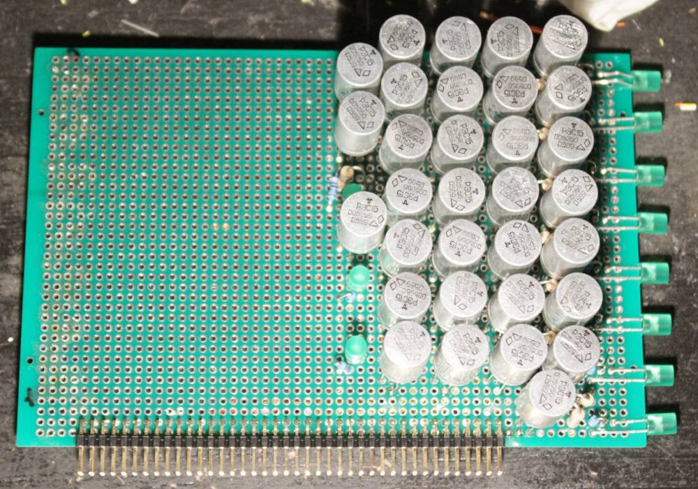
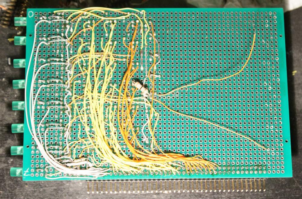
The control circuits will be pretty crazy too... I'm also building a carrier board/backplane to distribute all the contro signals.
Note: on this circuit I didn't manage the Vlatch and Vdrive correctly, the idea came after I soldered all the latches... So I split the 0V rail. The final version will have a split V+ but it will be "mostly compatible", at least for the connector, because V+ and 0V use 2 pins each. It's then a question of which pair to split.
Here I try to transcribe the connector's pinout:
| Function | pin# | pin# | Function |
| 0V latch | 1 | 2 | 0V drive |
| V+ latch | 3 | 4 | V+ drive |
| H (R7 out) | 5 | 6 | G (R6 out) |
| F (R5 out) | 7 | 8 | E (R4 out) |
| D (R3 out) | 9 | 10 | C (R2 out) |
| B (R1 out) | 11 | 12 | A (R0 out) |
| Sel1 | 13 | 14 | Sel1 (return) |
| Sel1 | 15 | 16 | Sel1 (return) |
| Sel1 | 17 | 18 | Sel1 (return) |
| Sel1 | 19 | 20 | Sel1 (return) |
| Sel1 | 21 | 22 | Sel1 (return) |
| Sel1 | 23 | 24 | Sel1 (return) |
| Sel1 | 25 | 26 | Sel1 (return) |
| OverwriteH | 27 | 28 | Sel1 out |
| Sel2 | 29 | 30 | Sel2 (return) |
| Sel2 | 31 | 32 | Sel2 (return) |
| Sel2 | 33 | 34 | Sel2 (return) |
| Sel2 | 35 | 36 | Sel2 (return) |
| Sel2 | 37 | 38 | Sel2 (return) |
| Sel2 | 39 | 40 | Sel2 (return) |
| Sel2 | 41 | 42 | Sel2 (return) |
| OverwriteF | 43 | 44 | Sel2 out |
| SelWr | 45 | 46 | SelWr (return) |
| SelWr | 47 | 48 | SelWr (return) |
| SelWr | 49 | 50 | SelWr (return) |
| SelWr | 51 | 52 | SelWr (return) |
| SelWr | 53 | 54 | SelWr (return) |
| SelWr | 55 | 56 | SelWr (return) |
| SelWr | 57 | 58 | SelWr (return) |
| (0V?) | 59 | 60 | Result (WriteIn) |
| Latch | 61 | 62 | Latch (return) |
| WriteBack | 63 | 64 | WriteBack (return) |
| 65 | 66 | ||
| 67 | 68 | ||
| 69 | 70 | ||
| 71 | 72 | ||
| 73 | 74 | ||
| 75 | 76 | ||
| 77 | 78 | ||
| 79 | 80 |
Only 8 pairs left...
- 2 pairs : Cin-Cou, /Cin-/Cout
- 2 pairs : F0, F1, F2, F3 (ALU)
- 1 pair : Carry enable (+return)
I can still add 4 pairs but it will be pretty delicate.
Yes, splitting the supply rail is a requirement. Apparently the best working voltage for Vlatch is in the range 3.2V-3.5V and could vary from board to board. A 3.3V regulator would fit...
Discussions
Become a Hackaday.io Member
Create an account to leave a comment. Already have an account? Log In.