 Jarrod
I've been doing some work on this project, haven't gotten around to documenting it, so here is a run down:
- Talked to a group of people who have an electric smart car and are working on reverse engineering the CAN protocol, see http://illuminatimotorworks.org/blog
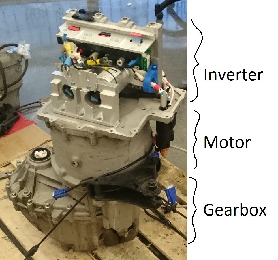
- I took a stab at it myself with the CAN datalog files they have. Could get the DC/DC converter operating but not the motor spinning. I decoded a couple of the CAN packets and worked out the checksum byte (it's "CRC-8/SAE-J1850" btw) and the structure of a couple of the packets but there are too many unknowns. Right now I've put this in the 'too hard' basket, may revisit. Perhaps I'll head over to St. Louis for one of their hackathons.
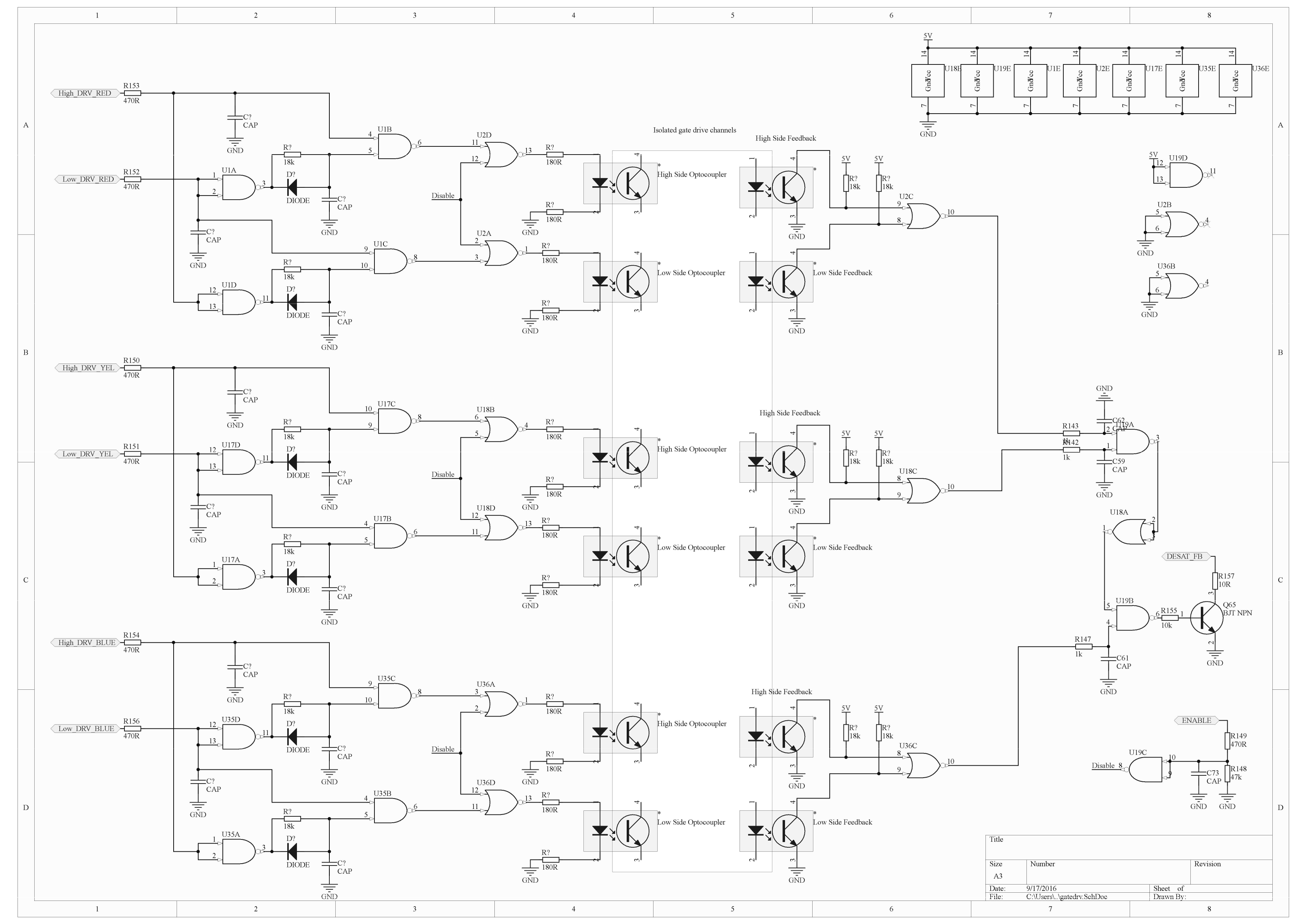
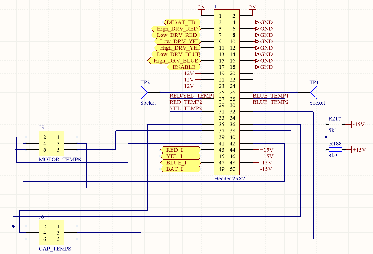
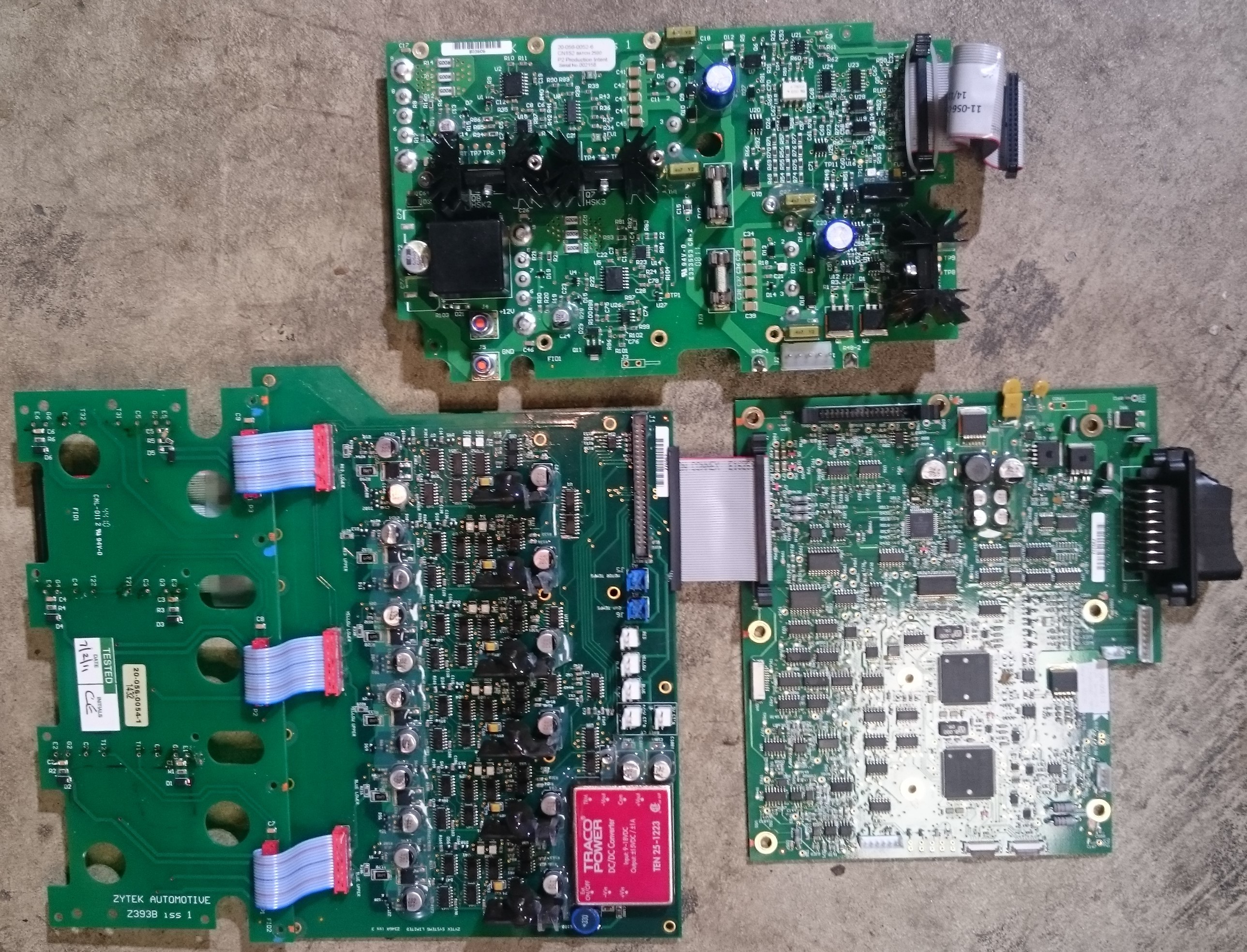
- Finished laying out a PCB for my replacement control board (using a TI Piccolo launchpad running InstaSpin much like my ebike controller) Got this board spun and assembled.
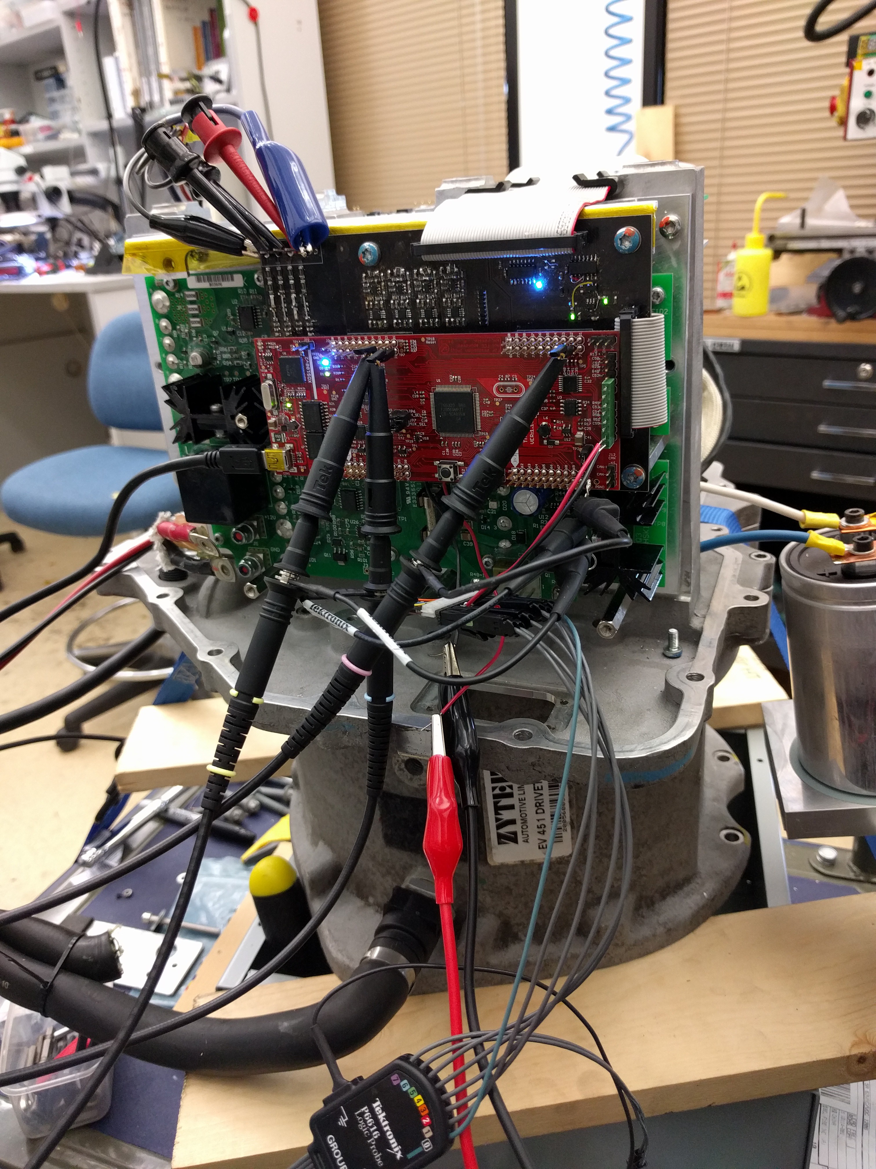
- Attached the control board to the gate driver board and current sensors, got the motor analysed and spinning with sensorless FOC. Messing around with firmware examples I got it working with the position sensor, although having trouble with the transition from sensored to sensorless.. work in progress.
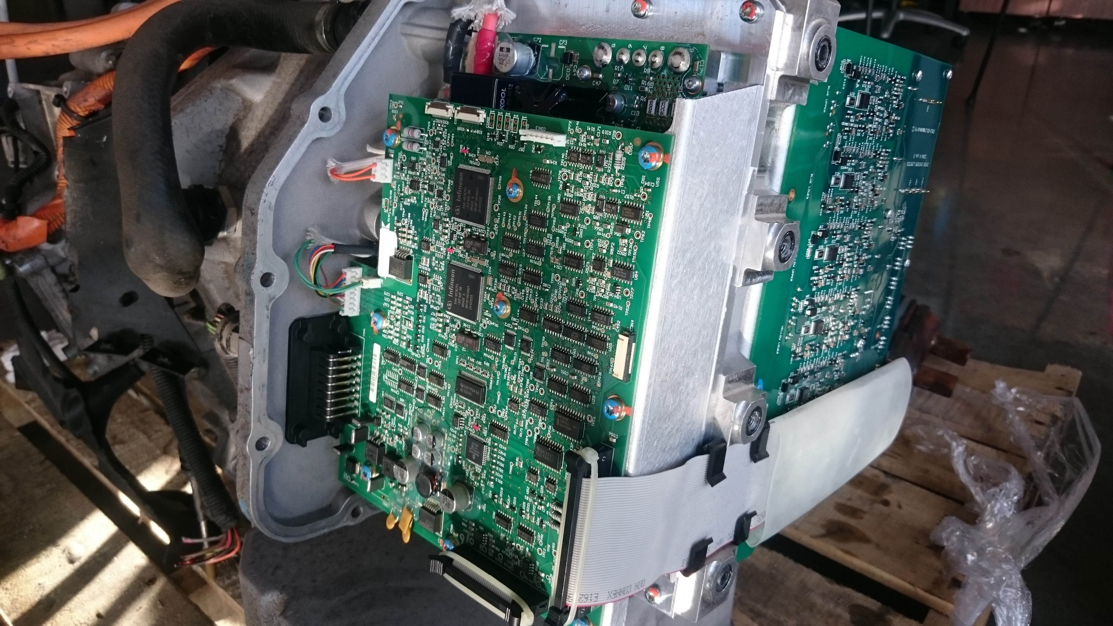
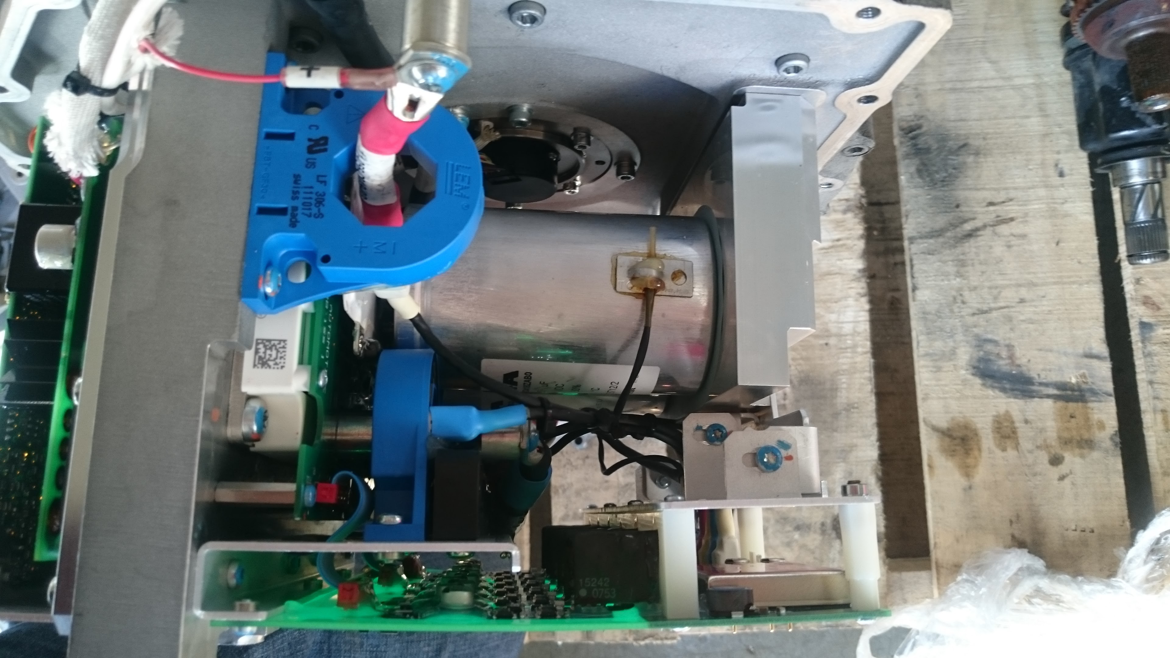
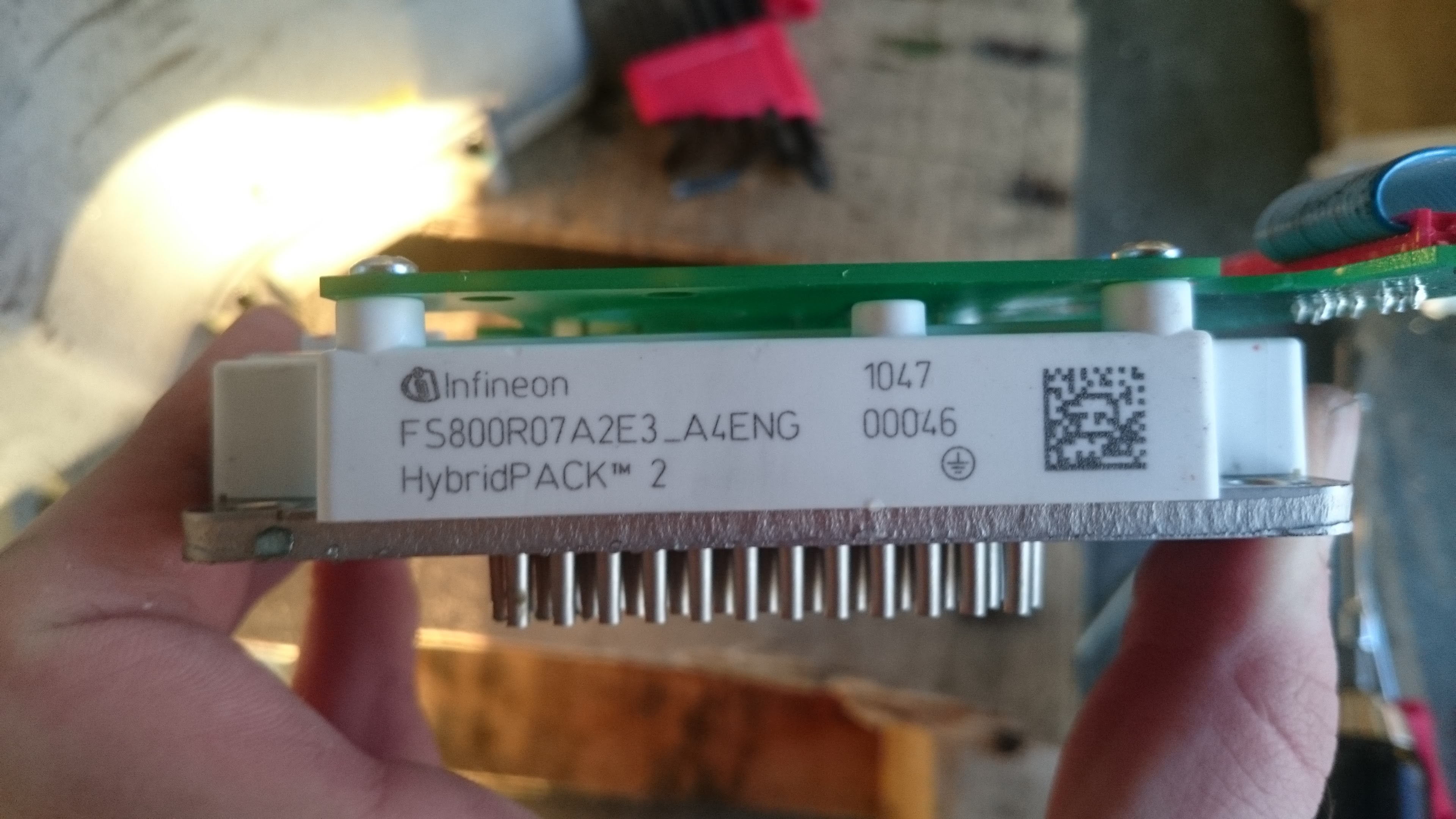
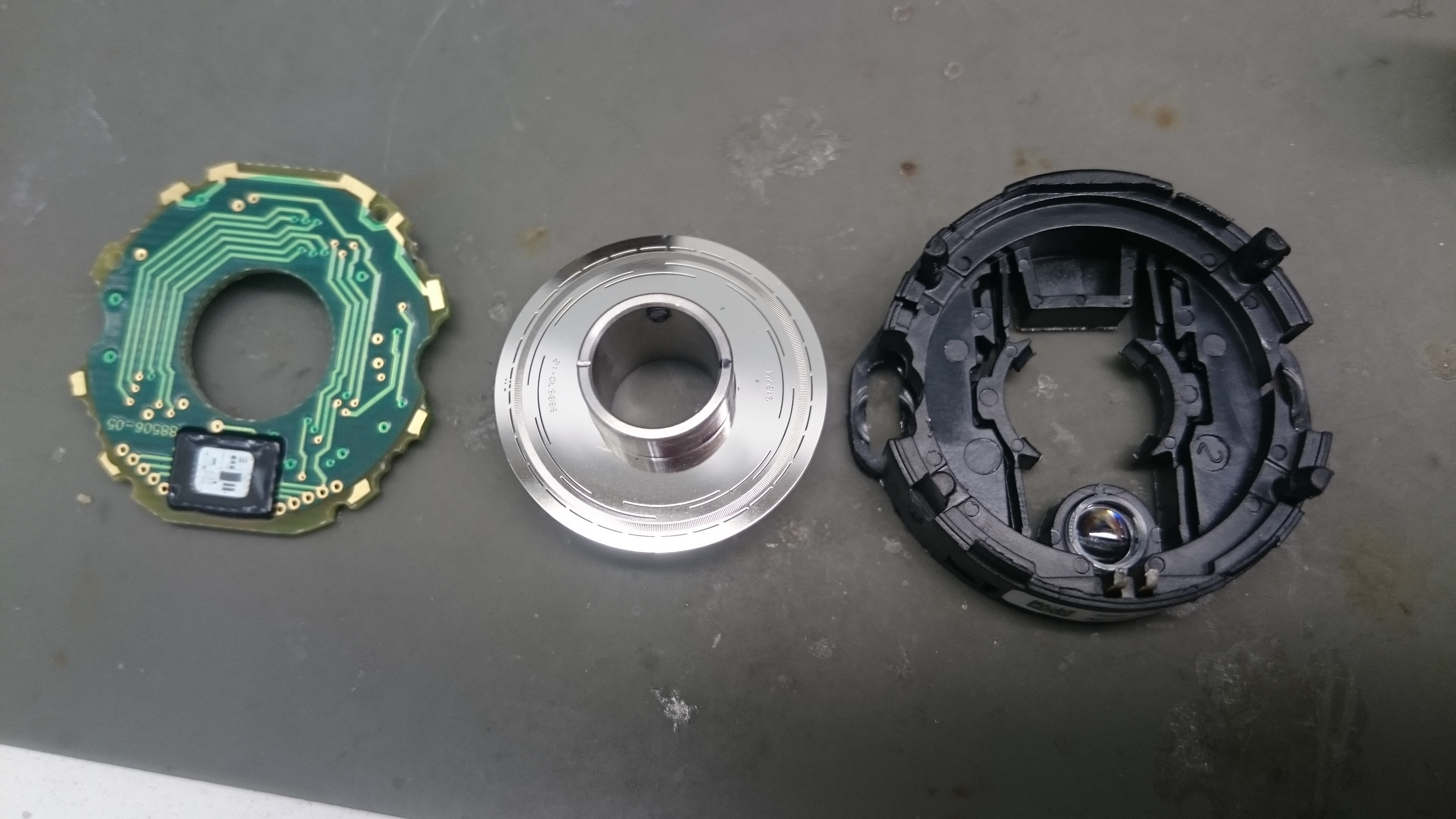
Pictures are fun, so here is the assembly:
I'm keeping my github up to date with hardware and software files. will transition the Altium files to CircuitMaker shortly.


 Christopher Xu
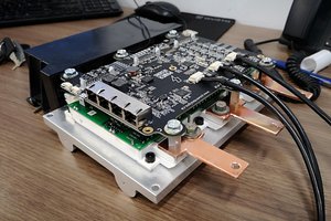
 Marcos
 ottoragam
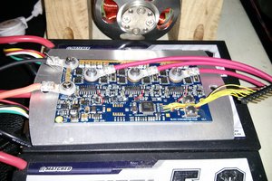
Hi Jarrod,
Any thoughts on this over the past couple years? Would love to hear if any updates.