 Jarrod
After much probing and a few datasheets I've got a pretty good idea of how the gate drive board works and what it's pinout is!
It looks like they put a fair bit of logic on the gate drive board mainly to ensure shoot-through never occurs. Shoot-through is when both switches in a half-bridge (ie one half of a H-bridge) turn on at the same time, causing excessive current as the rail is essentially short circuited. As you can imagine this is pretty destructive, so they don't want any noise from that long ribbon cable causing false pulses into the gate drives. The on board logic ensures only one switch in each half bridge can be activated at any time plus it inserts a dead-time between them. A master enable line can also shut down the entire circuit.
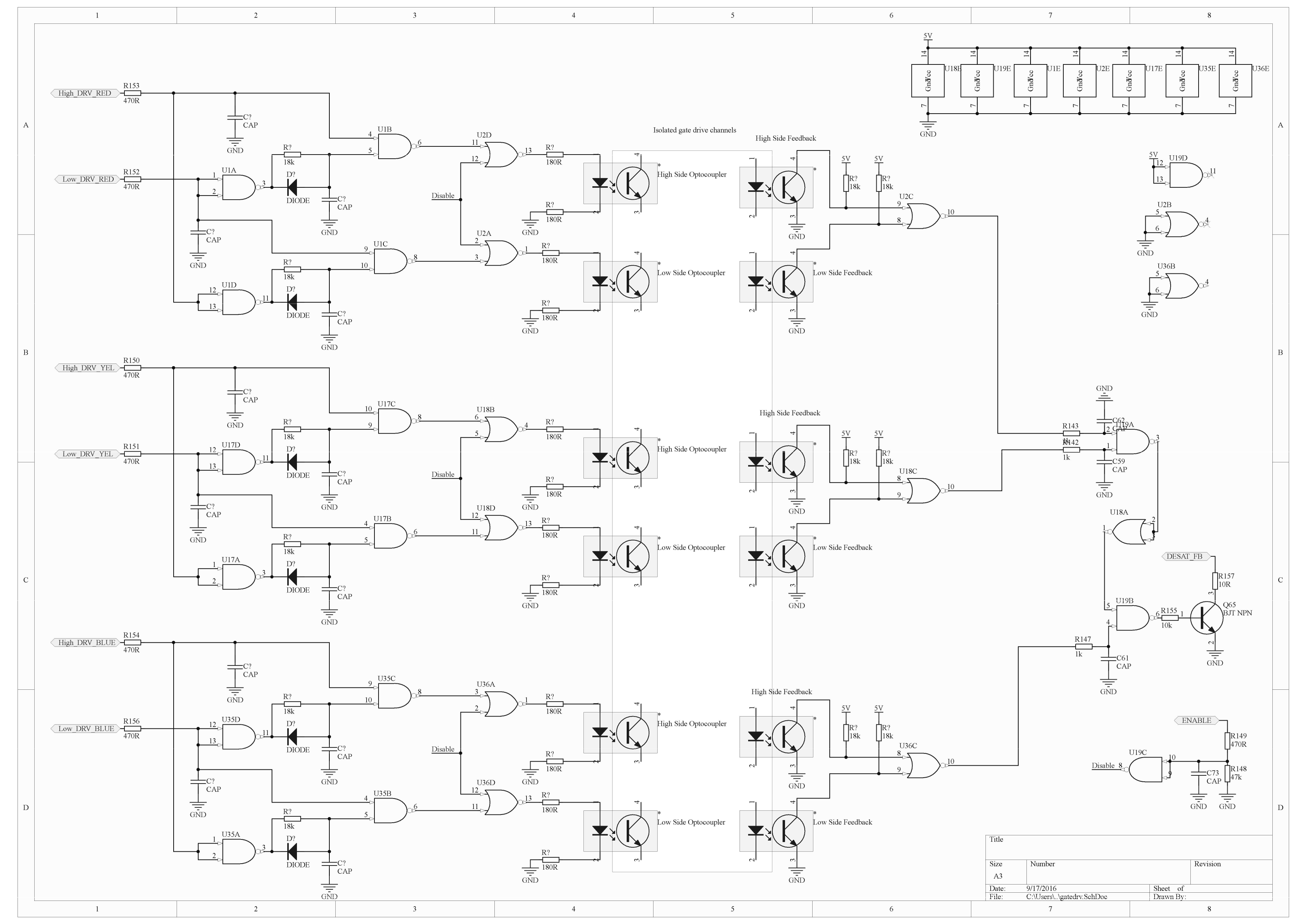
In the middle is the isolated (by optocoupler) gate driver stage. I didn't bother tracing this as it's quite complex and should behave predictably given how clear the function of the above circuitry is. Also not shown is the isolated dc/dc +/- supply for each gate driver, these all run off the 12V rail. and are rated at 2.5W.
On the right is feedback for IGBT desaturation, this is a common function in IGBT drivers where the Vce voltage is monitored while the switch is on, if the current becomes greater than the bipolar transistor saturation current, it will desaturate, enter the transistors linear region and Vce will rise, triggering the protection circuit. This is an effective over current protection mechanism as long as the switch is turned off quickly enough (full current with a large voltage burns a LOT of power, think >10KW as heat - the IGBTs can only dissipate this for so long..)
All 6 desat outputs are effectively OR'ed together (if you remember your boolean gate transforms) and sent back to the control board with an open collector output.
The connector pinout looks something like this:
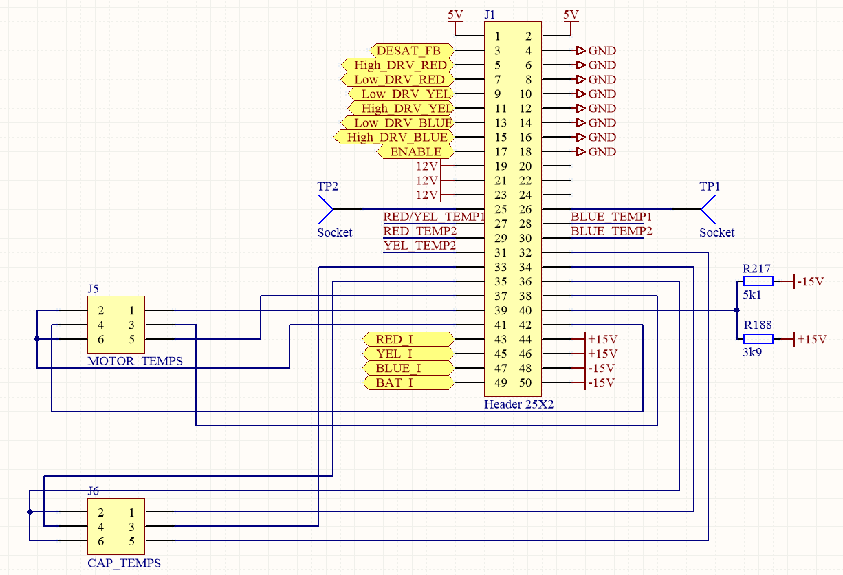
This all should be enough info to start designing a controller board.
Discussions
Become a Hackaday.io Member
Create an account to leave a comment. Already have an account? Log In.
Hi there!
I must thank you in your hard work so far. I've been visiting this page back and fourth for a while now while waiting for better weather (pretty cold where I am).
A little info about my project... I have two of these zytek motors and I plan to do some sort of eAWD where each motor would drive an axle only electrically connected. The plan right now is to have one controller talking to each motor. I plan to use an Arduino to do this (I understand there may be processing power limitations but I have some time on my hands so I figure I can massage things into place).
It seems youv'e outlined that J1 on the gate driver board is the most important connector for making your own controller. I was thinking of using the the 400>12VDC board to drive the sources required for the other boards. There is a connector that goes to the 400>12VDC board to the Zytek controller board. I was hoping you would have an idea of the following...Do you have any idea if the controller can hinder the operation of the 400>12VDC board? Also what is the lowest input required for the dc-dc converter to turn on? I don't posses a 400vdc source right now but I am looking into throwing together a step up transformer/circuit just to test everything minus the controller.
How goes your efforts? Thanks!
Are you sure? yes | no
Hey, sorry for the late reply, hackaday doesn't notify of comments on logs..
The DC/DC board is for sure able to be controlled via it's connector, It will require some effort to work out how though! But you don't even have to interface via the internal connector, you can simply send the motor a CAN message to enable the 12V output, these guys have worked at least that part out, http://illuminatimotorworks.org/open-source-documentation-for-smart-fortwo-electric-drivetrain
seems ID 0x112 messages enable the 12V output, the message has some other as-yet unknown function too as the data changes during runtime.
I'm currently working out how to control the motor from the CAN dumps these guys have provided. Their team is working on this as well. Once the protocol is known it will be relatively easy to control two motors from an Arduino, although it will probably need to be the ARM based Due, this is the logical choice thanks to a great project designed to drive other EV drivetrains: https://github.com/collin80/GEVCU
Are you sure? yes | no
Hey, no prob!
Yes this is exactly what I was looking for, although I must be honest I was hoping the Controller board did not use CAN to enable the DC/DC board. But that's alright, as long as I can communicate with the the DC/DC board everything else seems straight forward. Based on your suggestion and the recent info, you're right the DUE looks like the best bet. Thanks man, if I stumble across anything I'll be sure to pay it forward and share.
Cheers!
Are you sure? yes | no
yep all you need is a due and a Can transcever like the mcp2562 (it has 3v3 Io and 5V CAN), mount it on a MEGA breakout board.
The due actually has two can busses so it's feasible to drive both motors.
I also have a couple of MOSFETs to switch the 12v ignition line. I'll post a schematic and a fork of GVRET Arduino software soon
Are you sure? yes | no
I picked up the CAN-BUS shield from sparkfun https://www.sparkfun.com/products/13262
As you mentioned it uses a similar chip to the mcp2562.
I did not realize the Due had two. I was actually somewhat concerned about that since I would be trying to talk to both on one CAN line. I was starting to think about device ID's and if each motor would have the same.
Seems I would need two CAN shields to use both motors. That's all right for now. I'll just focus on one motor.
Well sounds good, I'll post a schematic too, just to share once I get that far! Cheers and good luck!
Are you sure? yes | no
The Due actually has the CAN controllers built in, so you only need to add transceivers, the board you bought has SPI CAN controllers and transceivers. this will probably require another library and CPU overhead to get working.
Are you sure? yes | no
Ah I see, thanks. I'll see if I can pick a couple. I'd rather not have the overhead.
Are you sure? yes | no
Hi Jarrod,
How goes your project? I wish I could say mine was doing better. I had some questions I was hoping you might be able to help me with or point in a direction where I may find helping info.
I've acquired all I think I need and wired everything up for a test bench scenario and I've tested my CAN Due ports for sending/receiving and acknowledging and I've also read through the open source documentation provided by Illuminati.
I have still not been able to get the DC/DC to turn on by sending the 0x112 message. I did so by pulling out the 8 byte data from the provided logs on the Illuminati site. There seems to be various messages sent under the ID 0x112 so I made my program on the Can Due cycle through all that I identified in the log with a delay of 11 seconds between sending the next message. Still nothing.
That said there are at least two gleaming questions that I asked Illuminati about but some of it still seems unclear.
In reference to Illuminati's 23 pin diagram of the OBD they list "Log Can H/L" as pin 1 and 9 respectively which I believe to be CAN for DC/DC comms but later they say DC/DC comms is on pins 16 and pin 17 which is labeled as "HV interlock In/Out" respectively. Considering their instruction is to bias pins 16 and pin 17 with +1.15V and -1.15V I do not believe we can use pin 16 and pin 17 for DC/DC comms. Leading me to my original thought about "Log Can H/L" mentioned above. The only other CAN signals labeled on the connector is "ED Can H/L" which would be for the electric drive according to the blog.
I have tried pin 16/17 for DC/DC comms just for giggles and it still would not turn on. Any idea what I might be missing?
This is a lot of info but I really do appreciate any help. Here are some details on my testing:
-"Log Can" is tied to Can0 on the Can Due. "ED Can" is tied to Can1 on the Can Due.
-300V is supplied to the Zytek motor with correct polarity. (Using a power supply that has no problem supplying current (4A @ 500V max) The DC/DC unloaded wouldn't need much current).
-"HV interlock in" has +1.3V "HV interlock out" has -1.15V (I will be purchasing LDO's to get the perfect value).
-I am using twisted pair for my Can wires.
-Termination is correct and my Can signals are square with some visible noise from the power supply (Similar to this picture on this site>> http://www.electronicproducts.com/Test_and_Measurement/Bandwidth_consideration_in_oscilloscope_selection.aspx).
-Continuity is verified into the motor housing on the terminals inside the case.
-message length is set to 5 in the Can Due according to the logs provided.
-I've tried both big and little endians for the Can message.
-Steady state voltage of my Can0 with the motor side connected is about 1.8V. Based on troubleshooting some documentation says an idle canbus should be 2V minimum. My bus only hits 1.8V when the motor side is connected.
I am more or less out of ideas right now. I asked illuminati about pin 2/9 vs pin 16/17 but no reply yet. Any idea what I am misunderstanding?
Thank you for any help you can give and cheers!
Are you sure? yes | no
Kevin's instructions don't look like they were proof read by the guys doing the technical work, so unfortunately there are some mistakes. Use the wiring diagrams, not the text. Use pin 2/10 for CANH/CANL and pin 16/17 for interlock in/out.
Ignore the voltage they say to put on the interlock pins. tie pin 17 to gnd and pin 16 needs a 20mA current source (this results in 1.15V across pin 16 to pin 17) I do this with a 200ohm resistor between pin 16 and +5V rail on the arduino.
I'll post a CAN file that I used to get the DC/DC converter going. So far, that's all I've been able to get working. I still can't get the motor to spin with the CAN dumps they provided.
In fact, I've decided to focus my efforts on creating a new control board again.
Are you sure? yes | no
Hi Jarrod,
Thanks for clearing that up. Hopefully I can get it turned on. I am not sure how useful this will be but back in July I made a brushless motor controller in anticipation of making my own ESC for the Zytek. It's based off of a smaller brushless dc motor I got from a hobby shop. It is also based on sensors. Below you will find a link with that brushless sketch and the sketch I used so far to try and get the DC/DC to turn on on the Zytek motor.
https://drive.google.com/open?id=0B0x9DUqlZUfSVXVXeWtvZnBtQVk
I also matched up Illuminati's logs (third sheet in the excel file) to try and grasp what corresponded to what, see that here...
https://drive.google.com/open?id=0B0x9DUqlZUfSVGJkeFZRNzgzNm8
I am unsure right now if the CAN messages are correct but it seems some of the signals are cyclical indicating possible rotation or sensing of rotation. Message ID's are 0x110, 0x115, 0x120, 0x125, 0x130 (seems to be the most promissing) and 0x165.
Hope that helps.
Are you sure? yes | no
I too have a BLDC motor controller project, it's more a hardware project, the software is a modified version of the TI instaspin motor control software.
https://hackaday.io/project/2484-everywhereelectric
I'm using a similar CPU for the Zytek control board. I've already had the PCB design made, loading it now.
I've also done some analysis of the CAN dumps from illuminati, I spoke to the guys and have some different files, the ones that 'work'. Kevin posted the wrong files to his blog apparently.
I've written a script to do some quick plotting of data as I work out what each byte in each message type does. I've also worked out the checksum byte used in a few of the messages. Anyway it's all in my repo now.
https://github.com/jarrod89/ZytekHacking
Are you sure? yes | no
Thank you, looks like I have some troubleshooting to do. I structured my code to send the appropriate messages/ids in sequence based on the messages you provided. The DC/DC still wont turn on. I've noticed that I do not seem to be receiving an acknowledge from the zytek. I've verified my connections. Not sure what I'm missing hmm.
Cheers
Are you sure? yes | no