 stefan.schnitzer
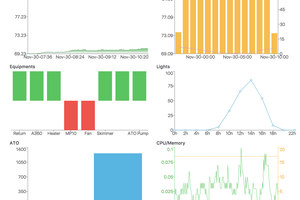
1. Demo of graphical HMI and Alexa voice control.
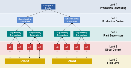
2. Functional levels of a manufacturing control operation (source:https://en.wikipedia.org/wiki/SCADA)
A DIY smart home system the SCADA way...
Already have an account? Log in.
To make the experience fit your profile, pick a username and tell us what interests you.
1. Demo of graphical HMI and Alexa voice control.
2. Functional levels of a manufacturing control operation (source:https://en.wikipedia.org/wiki/SCADA)
20191004_135146.gifQuick Demo of door monitoringGraphics Interchange Format - 6.53 MB - 10/12/2019 at 05:32 |
|
|
20190930_174021.gifQuick Demo of auto-refill functionGraphics Interchange Format - 12.91 MB - 10/05/2019 at 05:55 |
|
|
20190929_121927.gifQuick Demo of graphical HMI and Alexa voice controlGraphics Interchange Format - 10.46 MB - 09/29/2019 at 10:22 |
|
|
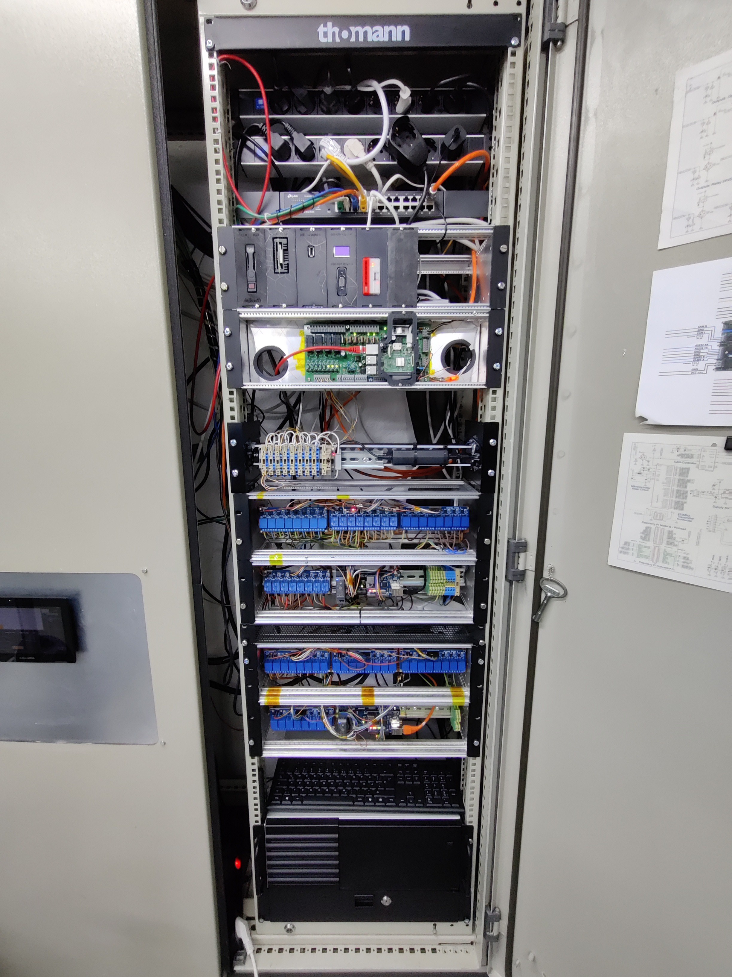
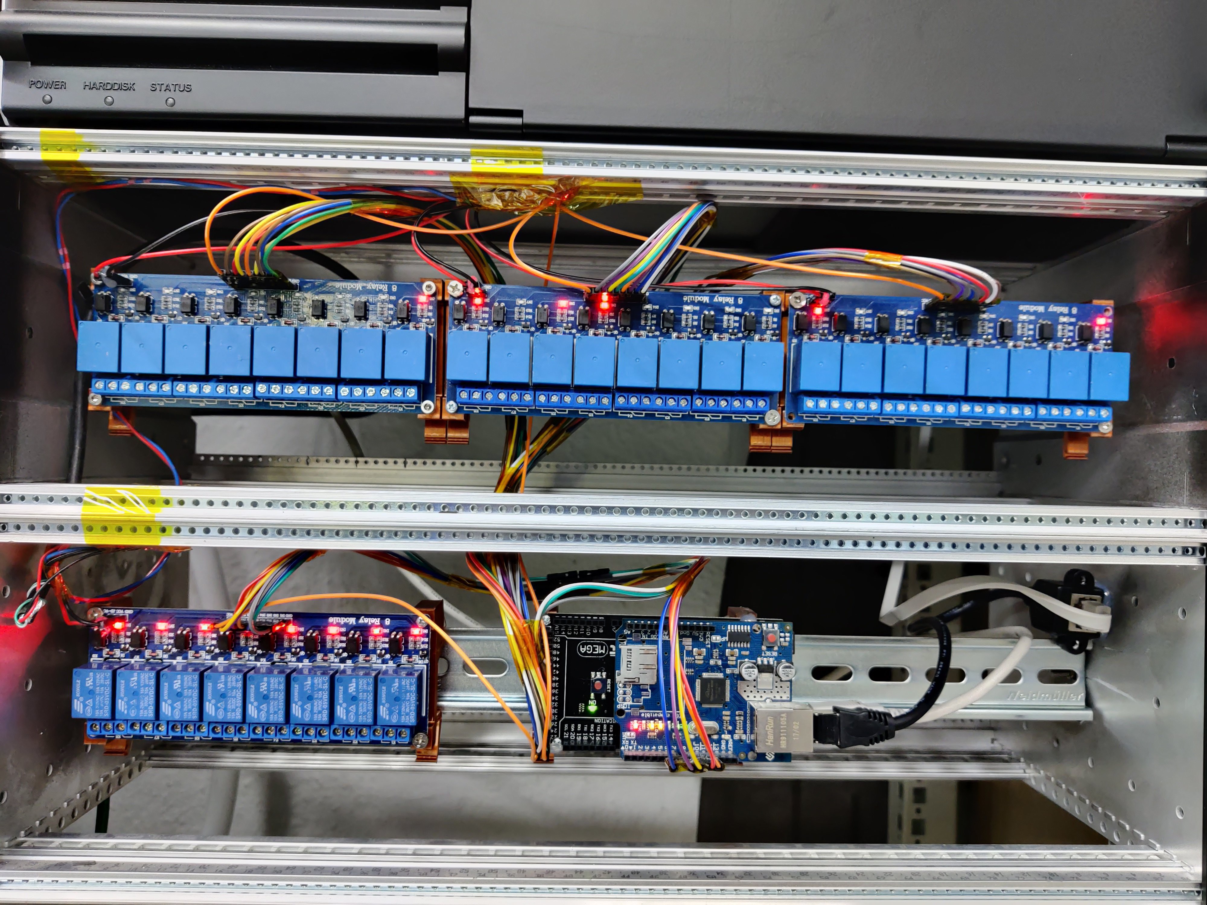
I finally managed to put all my raspberry pies into one cabinet:
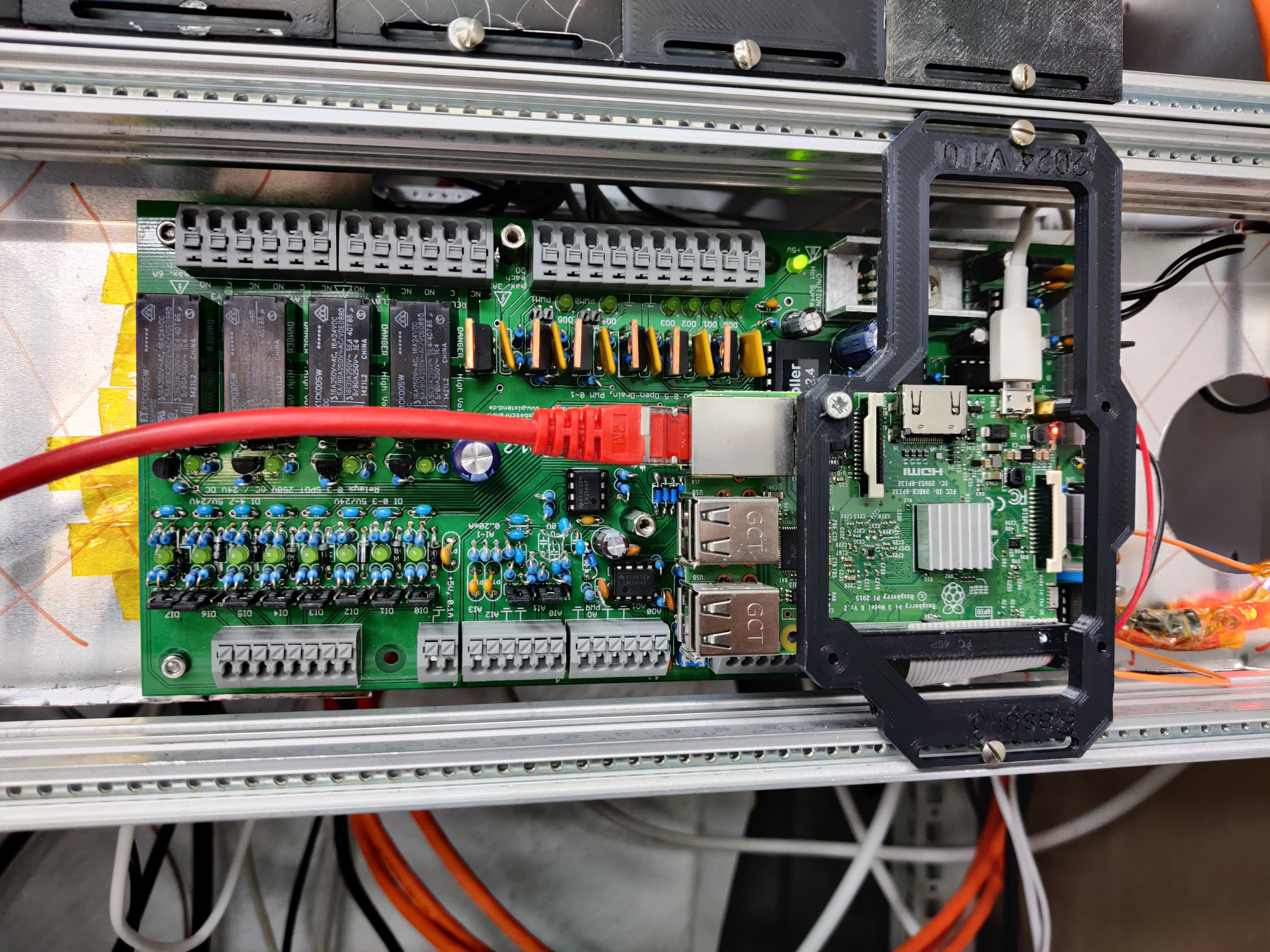
The heart of it all is still a Raspi3 with a codeSys SoftPLC running on it:
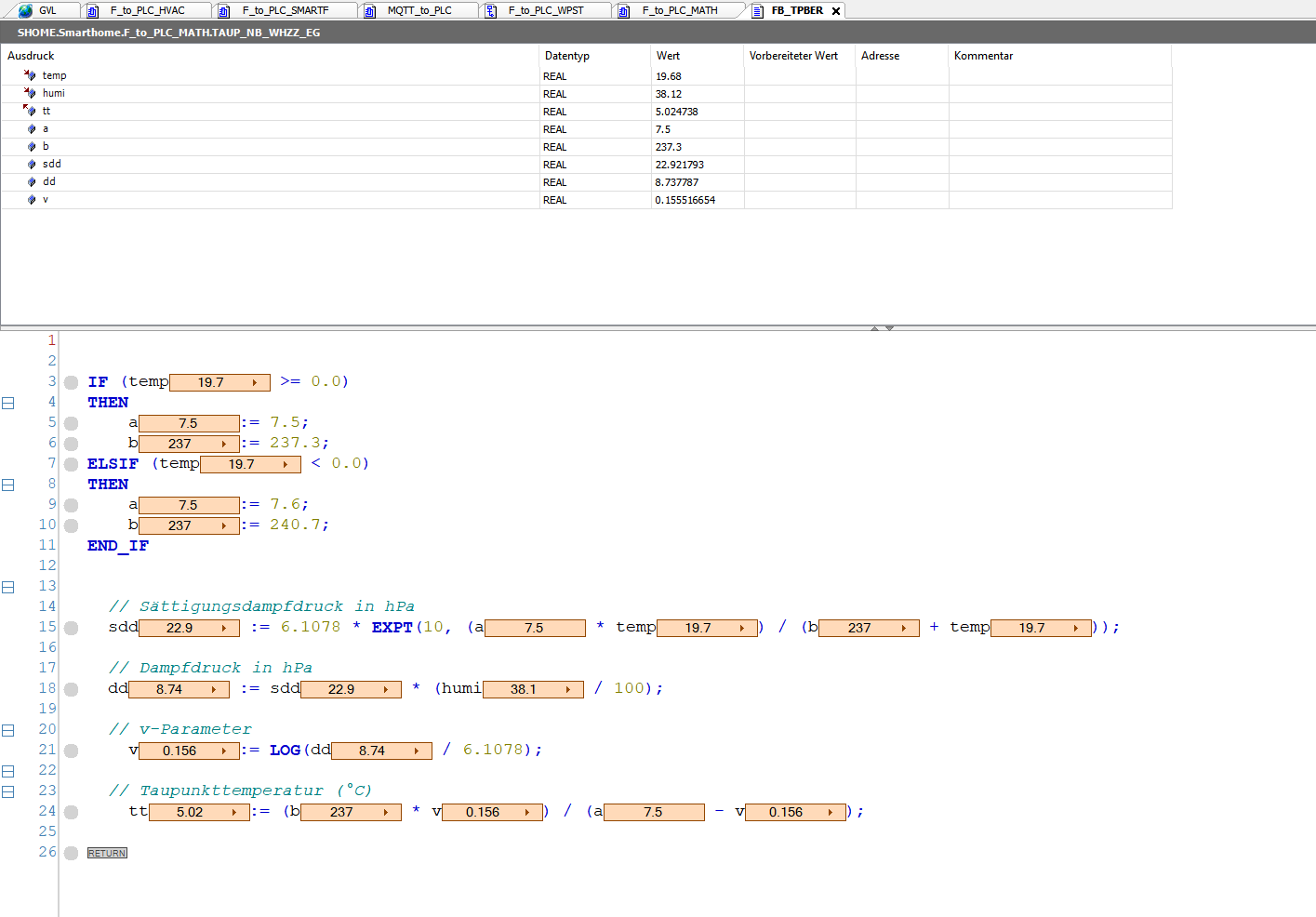
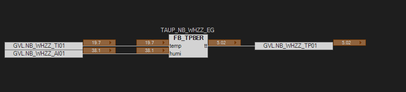
It is snowing here in Austria. So, I spent some time porting a dewpoint calculation method to SCL (ST) and made a Function Block (FB):
https://github.com/MakeMagazinDE/Taupunktluefter/blob/main/Taupunkt_Lueftung.ino
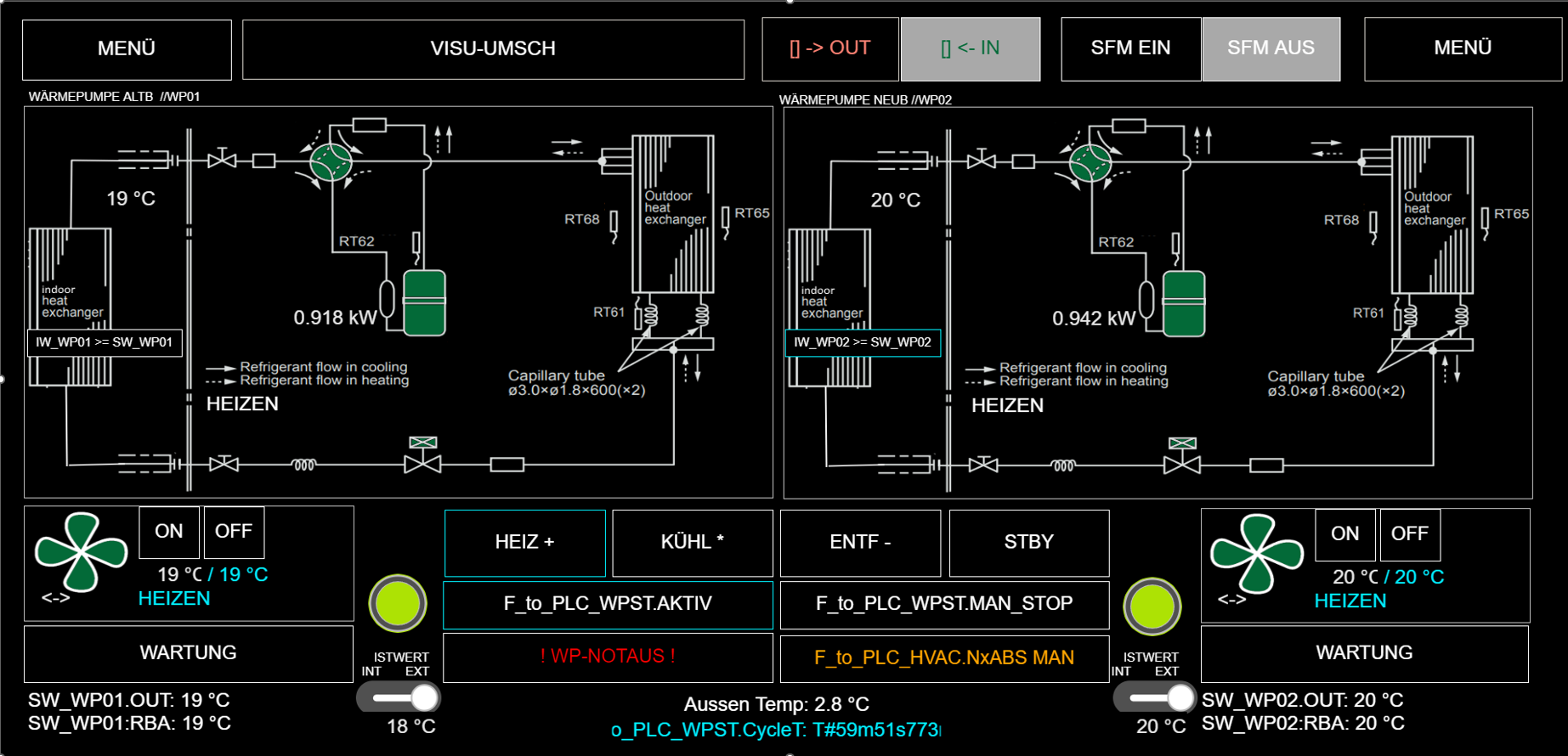
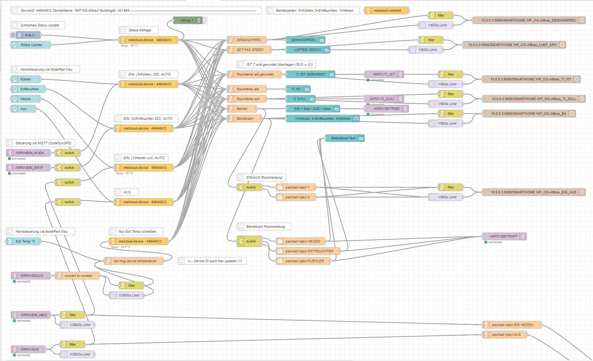
Playing with your smart home is all fun until it also controls the heating ;) I use the temperature readout from my home-buttons as an external reference to control two heat pumps via node-red. If the home-button fails (does not call for >35min) the PLC switches to the internal reference sensor.
Most of the control logic happens on the PLC level. Only the communication with Mitsubishis melCloud takes place on the nodered.
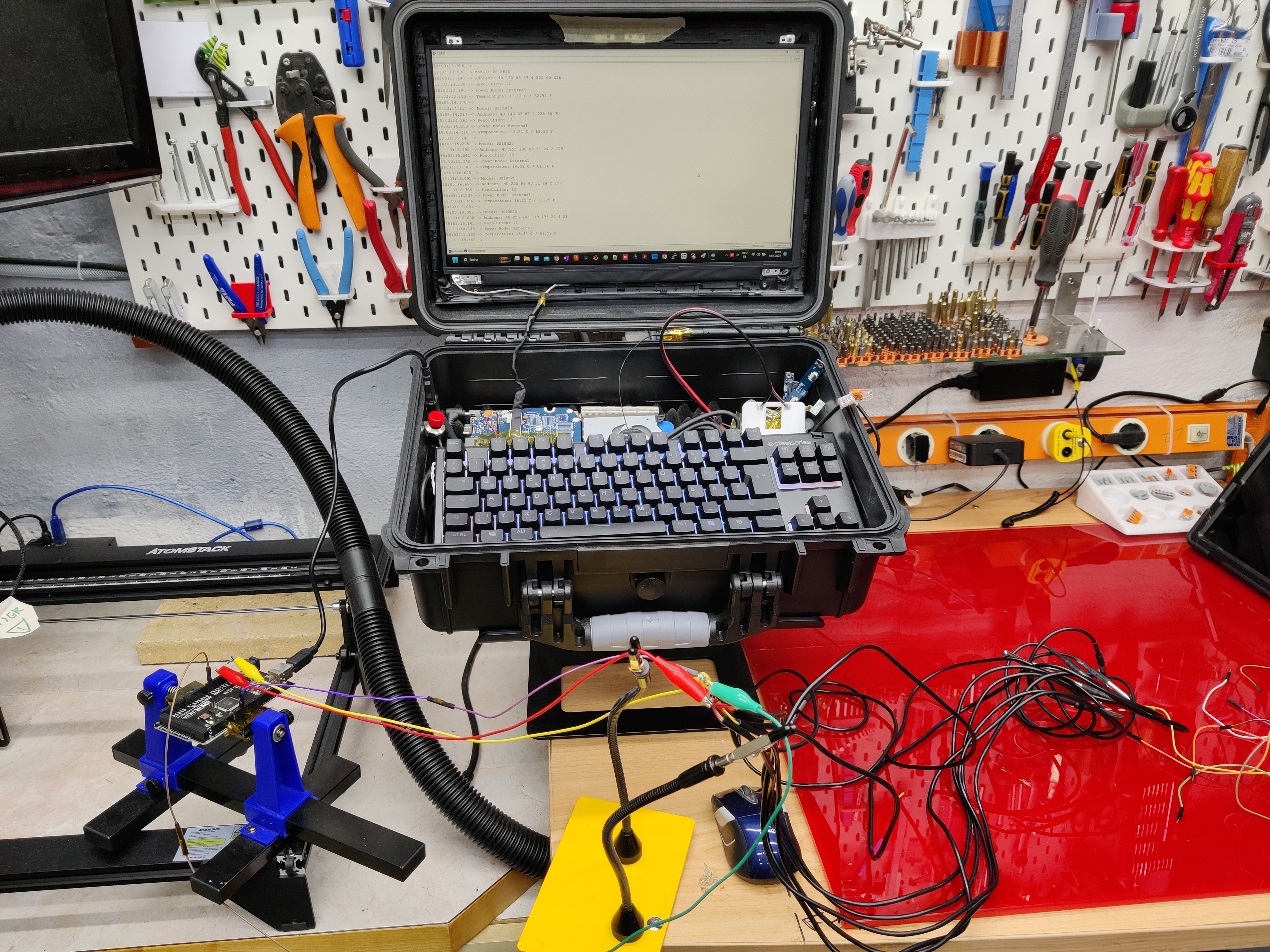
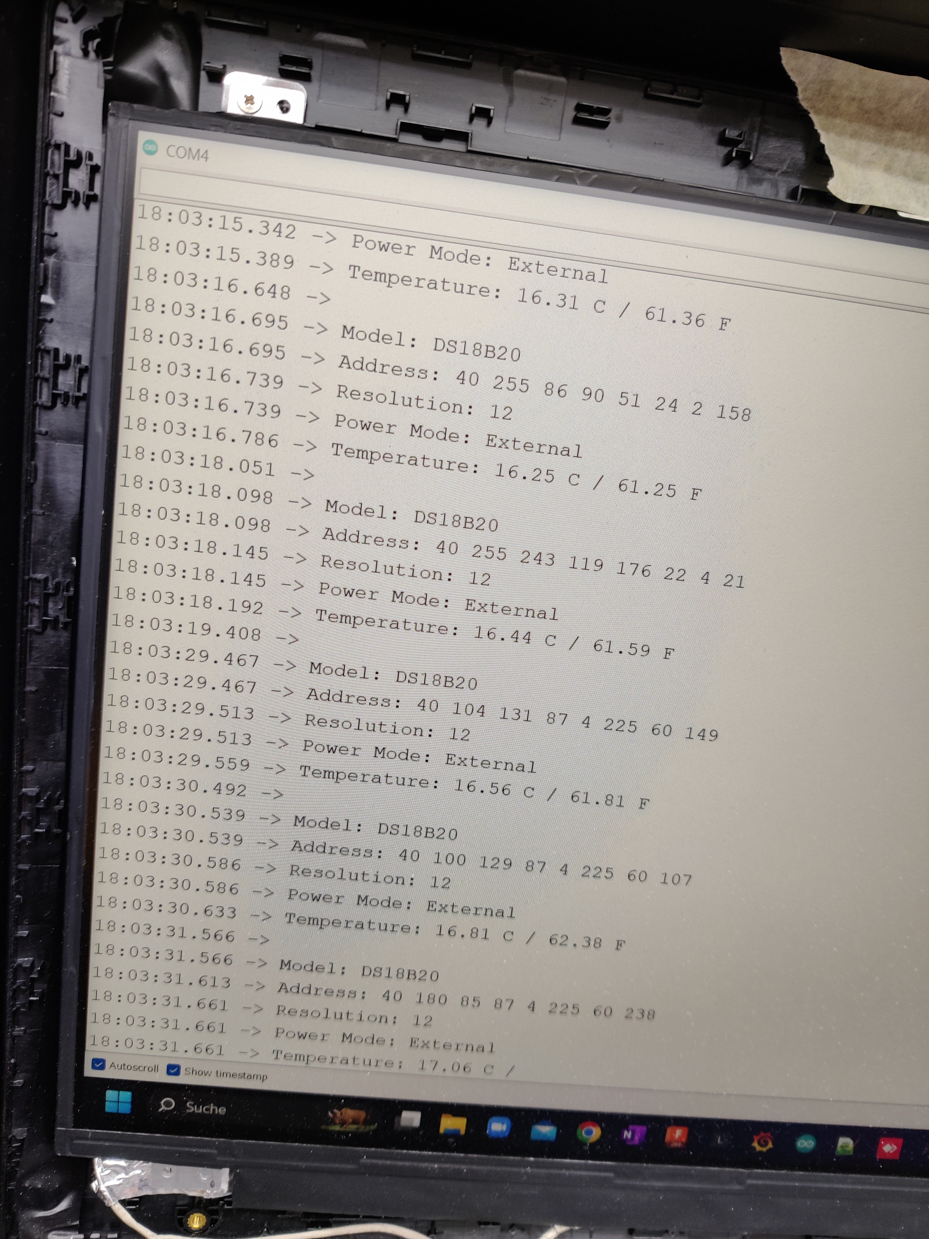
I was testing some DS18B20 Temperature Sensors. I hope to connect up to 8 Sensors via a 50m CAT cable to the AI-modules. (Arduino 2650)
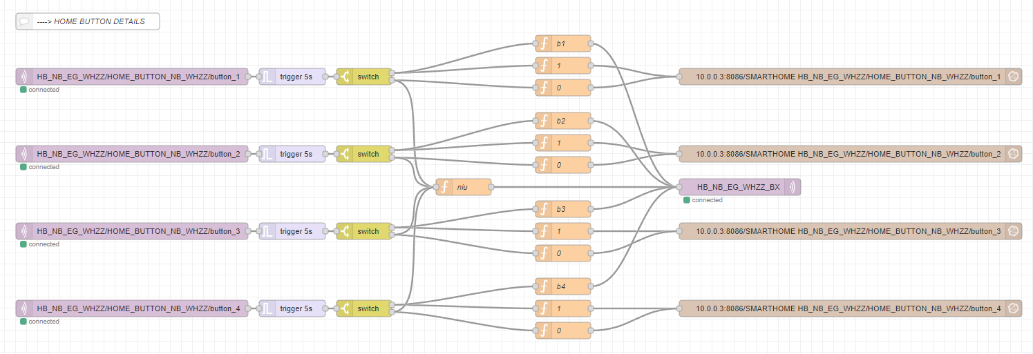
This is how I combine the messages from 4 buttons into one.
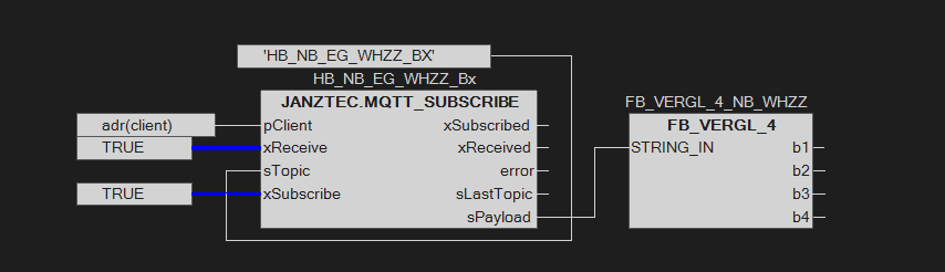
So my PLC does not have to subscribe to too many topics and I can use each button input as a boolean.
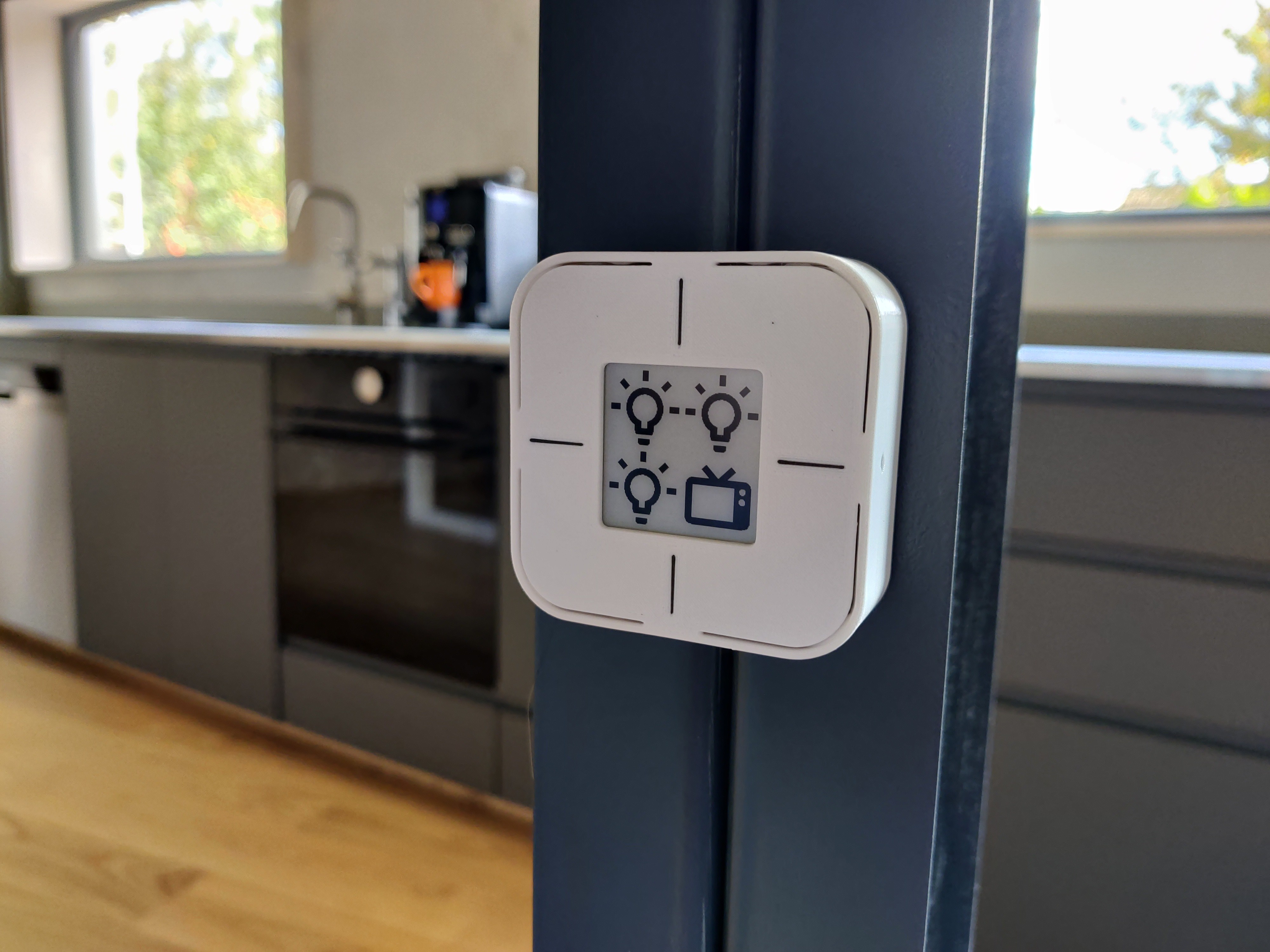
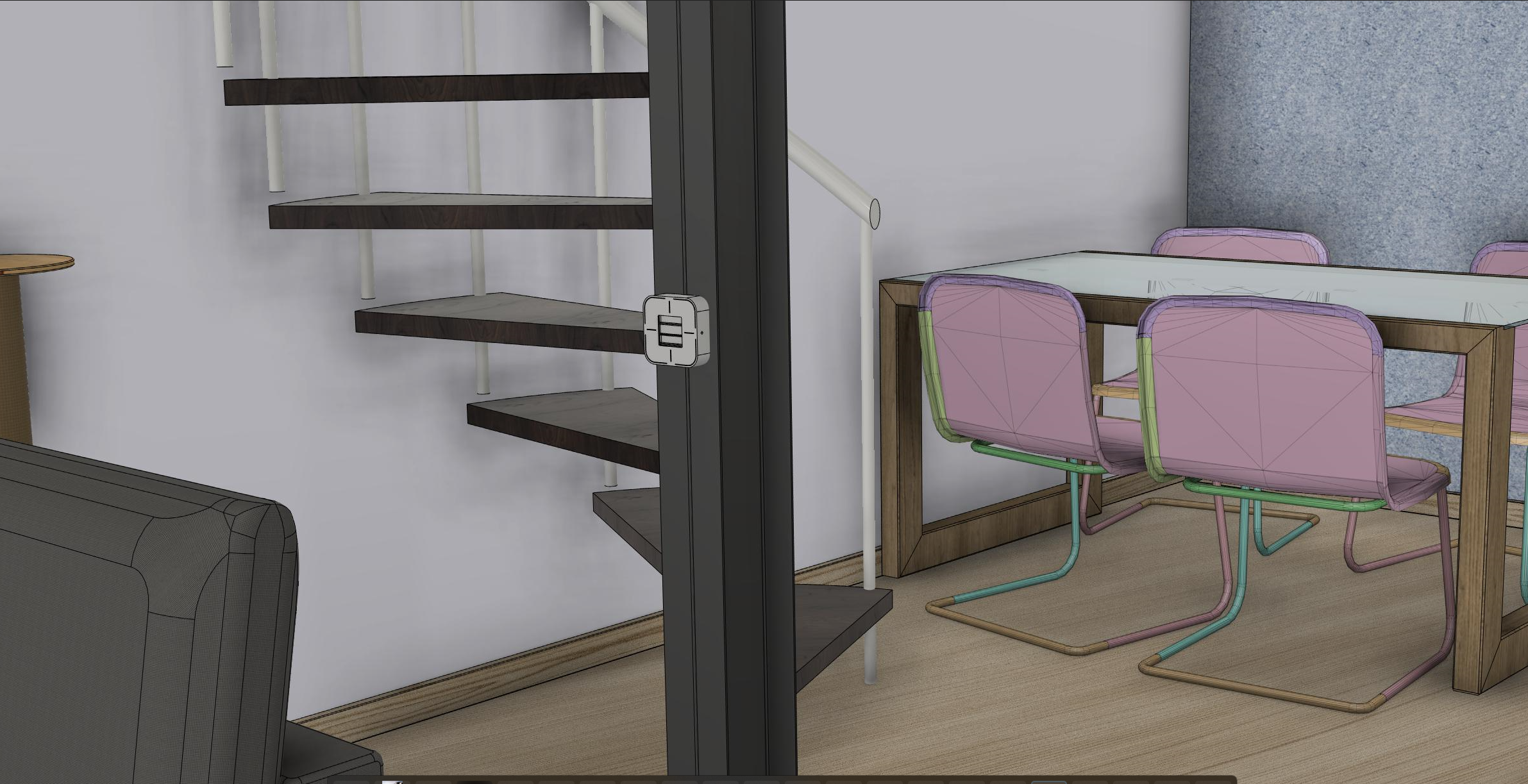
They look and feel great.
To save on MQTT-subscribing-blocks on my Soft-PLC (Codesys) I summarized the buttons in Nodered:
After contemplating a DIY solution for physical light switches I stumbled upon a listing on Tindie. These https://www.tindie.com/products/plab/home-buttons-mini/ have four buttons and transmit temperature and humidity via MQTT. So I decided to give them a try. -I'll update you as soon as they arrive.
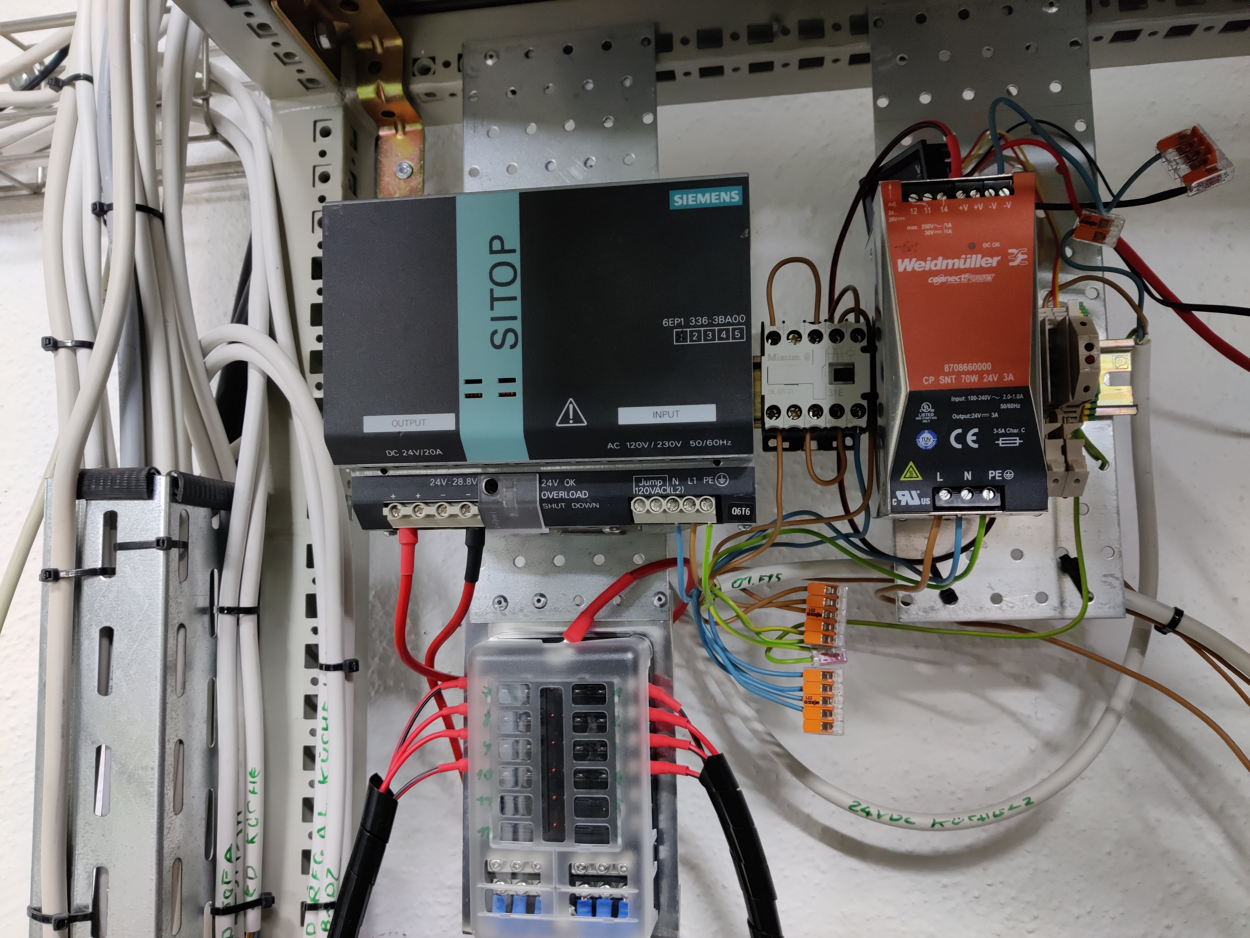
I decided to put two separate power supplies in. The bigger one is connected to most of the 24VDC-LED-strings (~300W) and the smaller PS supplies power to 24VDC IKea drawer lights and some utilities.
This helps to save on stand power because the big 480W supply only gets switched on when someone turns on a light. In contrast, the Ikea drawer lights constantly need voltage to switch on via their internal sensors.
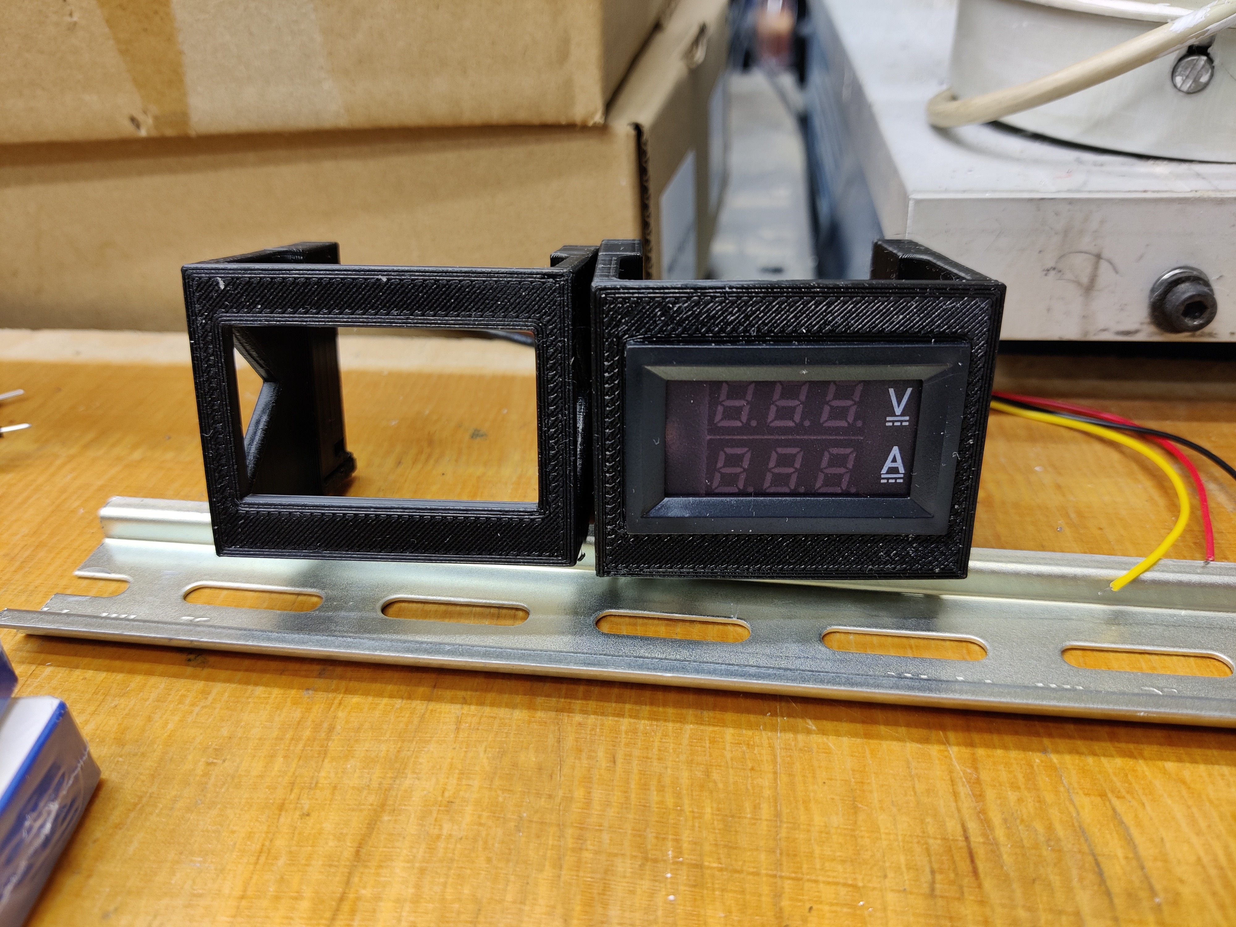
To monitor the load on each supply I bought two cheap volt + amp-meters from Amazon. (the DIN-rail-holder is from Thingiverse: https://www.thingiverse.com/thing:3486542 )
Finally, I am getting to build and test my new IO modules—all off-the-shelf parts except some small 3D-printed mounts.
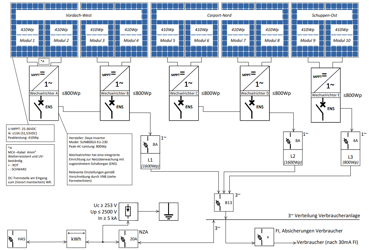
I recently installed a 4kWp PV-System ( 10 Panels connected to 5 Microinverters)
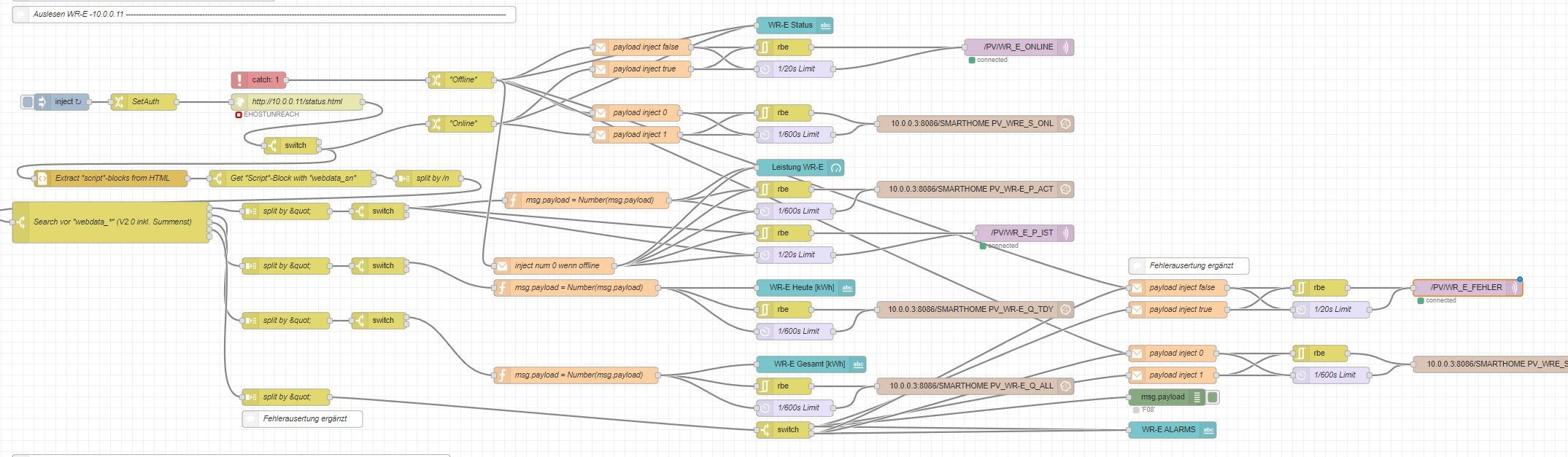
Naturally, I wanted to connect it all to my Smarthome. But the Modbus-TCP Interface of the Inverters (Deye SUN800) is not working for me. After browsing GitHub, I stumbled upon a solution (https://flows.nodered.org/flow/bf4e518f48eca5922ea3274680ac8692) to connect the web server of the inverter-data-logger. The web interface provides all necessary data like current power production, daily production, total production and fault codes. It works by logging into the web page via node-red and parsing the content for the needed data. After some filtering, the data is passed on to influx db (for grafana) and my smart home PLC via MQTT.
Now my smart home "knows" when "free" electricity is available and can switch on the car charger or the heat pump.


I love the fact that my simple door switches started a discussion about retrocomputing. That's why i like the hackaday.io community so much.
@Ken Yap
I used this principle (well known technique for analog instruments): http://www.excelautomationsolutions.com/post/how-a-4-20ma-transmitter-works.html

Hi, your link to the Wikipedia SCADA page is broken, the text is correct, but the link is not. Also without knowing anything I suspected the 4..20 mA loop is an industry standard with such specific numbers, and it is, so maybe link to the Wikipedia page for that too? Thanks!

@Ken Yap -- the 4-20mA current loop scheme is very well known in the retrocomputing community... specifically the part that messes around with the, er, bigger machines. Minicomputers and such. See, before RS-232 (and, in some cases, even afterward) it was the best way to send a lot of serial data over a distance. Teletypewriters used this basically until the video terminal killed 'em all off.
You need four wires, two for TX, two for RX. Power and ground... and, no, you absolutely *cannot* combine grounds here. You're basically driving an optocoupler (or an open-collector junction, in the much older days) from a rather significant distance, for each side of the link... hence the values for the current there, and the fact that the voltage can vary so widely. IIRC it's active low, so a 'mark' ("1") is when the thing dips to 4mA and shuts off the little light in the opto, and a 'space' ("0") is when it levels back up to 20mA and the light comes back on ;)
The niftiest side of this, is that because it's /current/-dependent and basically screw the voltage as long as it can light a friggin LED or whatever, you can run these things quite nicely over insanely long distances (multiple /kilometers/, seriously... I want to say I heard that the signal really only peters out irretrievably at something like the 2km mark, but I could be off there... I could easily see it being longer, especially with repeaters) if you don't mind the transmission rate being kind of low... like 9600 baud maximum, and closer to 300 baud or so for the longer trips. (Baud?! Of course, dude, back then *everything* was baud. Screw BPS, we want to send things with character(s), not one friggin bit at a time :P )
...oh, and MIDI is basically exactly this, but with tighter voltage specs and a really freakin' weird baud rate.
Yeah it reminded me of the current loop teletypes we used to run that's why I looked it up.
I used to have a Decwriter LA30 which I converted from current loop to RS232, see here: https://hackaday.io/project/161656-flashing-leds-from-old-printer-electronics
Trivia Q: What was the name of the console teletype in the original PDP-11 Unix?
A: /dev/tty8
True story: When I was a neophyte in Unix, I asked the local sysadmin/guru how to detect machine shutdown, save state and exit my program gracefully. He told me to catch SIGTERM. After I mastered that I ran a small program in the background that just blocked waiting for SIGTERM. The next time the sysadmin shut down the machine, he saw the console print out Arrgh, you dirty rat... which was the code executed on receiving SIGTERM. In those days permissions were a bit lax and the console (by this time not a teletype) was world writable. I think they fixed the permissions after that.
Here's a bit more of Unix history I set down for posterity in my professional blog, which is mostly about things to do with my day job or my home Linux setup.
https://green-possum-today.blogspot.com/2018/09/the-true-origin-of-nuxi-problem.html
@Ken Yap LOL, I should've known you tinkered with that stuff /personally/ back in the day... you lucky bastard :P I've been fascinated with retrocomputing since probably when Mom got me a now-ancient copy of "The Soul of a New Machine" by Tracy Kidder. Still have it somewhere... awesome book.
Dangit, I need to read that thing again.
...also, why #8...? I'd expect 0 or 1 but not 8... actually, also, what were the other 7+ TTYs doing, if not running the console...? Logging stuff?
I don't remember, you could check the V6 history or Unix sources online but I think the first bank of minor devices, either didn't exist, or were allocated to other devices. I think more likely the former and the Unibus (DEC aficionados will remember this) slot for current loop serial devices was at 1.
 Ranjib Dey
 Tom Gillispie
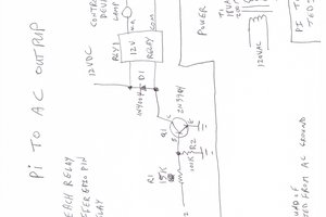
 Ted Mieske
 Ildar Rakhmatulin
SCADA is such an interesting branch of computing because they have techniques nobody else pays any attention to.
I've had a lot of success using my interpretation of tag point objects in Python, and I'm sure if I studied SCADA more I'd discover all kinds of stuff.