 Shervin Emami
All LEDs (including Infrared Emitter LEDs) produce light based on the amounts of current flowing through the LED. So to get the furthest range from an IR emitter LED, I want to put as much current through the LED as reasonably possible. If I put too much current through the LED, it will either die instantly or get hot very quickly and then die from overheating. And there's also the problem that LEDs have a very sharp voltage vs current curve, where feeding an LED just 10% more voltage than recommended will cause a significant increase in current, often killing the LED. That's part of the reason why instead of simply using a (current-limiting) resistor in series with the LED, high power LEDs are nearly always driven using a "constant-current" power source, to make sure the current stays fixed even if the voltage or battery level varies. Some examples of simple constant-current LED driver circuits are:
- Using a Transistor + 2 Diodes : "https://www.analysir.com/blog/2013/11/22/constant-current-infrared-led-circuit/"
- Using a MOSFET + a Transistor: "http://www.instructables.com/id/Power-LED-s---simplest-light-with-constant-current/step2/Specs-Function/"
- Using a MOSFET + a Voltage Regulator: "http://www.instructables.com/id/Super-simple-high-power-LED-driver/step2/How-it-works/"
For this project, it might turn out that I will need to use a constant-current power source. But I'm going to try to get by with just a current-limiting resistor. (Note that a "current-limiting" resistor is just a normal resistor). And if I'm not using a constant-current power source, I should probably at least use a voltage regulator so I have a constant-voltage power source for that resistor, but I'm going to try to get by without a voltage regulator as well! A constant-current power source has the advantage of giving good control of the current to the LED for safety, as well as being more efficient than simply using a resistor. But by powering the LED just for very short bursts, and not pushing the LED quite to its limits (since I'm not aiming for the absolute longest range possible from the LED), I'm hoping the LED might be used near its limits but won't blow and also it shouldn't be too inefficient since the LED would be off most of the time.
This means I need to be very sure I don't power the LED long enough for it to overheat, and make sure I stay within absolute ratings so it doesn't instantly blow the LED even when the battery is slightly overcharged. According to "http://electronics.stackexchange.com/questions/55823/how-can-i-efficiently-drive-an-led", when simply using a current-limiting resistor I should put atleast 25% of the voltage through the resistor to ensure there is enough voltage difference for the LED to operate in. Assuming the device is powered directly from a single-cell rechargeable LiPo battery, the battery voltage would be between 3.3V when flat to 4.2V when fully charged. LEDs are nearly always less than 2.0 V, so this means there is enough voltage gap for the current-limiting resistor to cover atleast 25% of the voltage when in series with the LED.
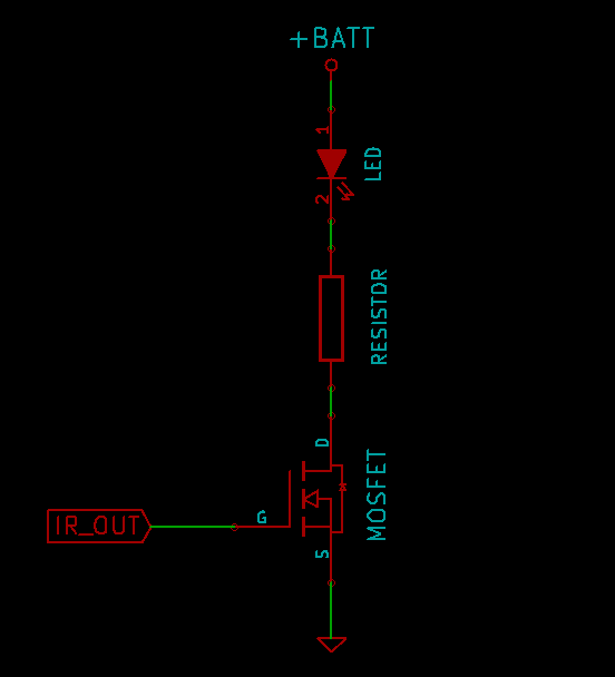
So the LED driver circuit I'll use is as simple as:
Note that using such a simple LED driver while still trying to reach roughly 50% of the absolute max rated current means I need to be sure the microcontroller only leaves the LED on for very short durations, and leaves it off for majority of the time. The datasheet figure below shows the effect of pulse length and duty cycle for the Vishal TSAL6100 Infrared emitter LED, showing that the LED can handle several times more current if it's a very rare pulse (eg: tp/T = 0.01) compared to something like a pulse with 0.5 duty cycle (ie: switched on half the time and off half the time).
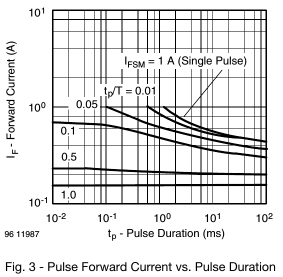
Looking at the datasheets for 2 IR emitter LED's I've been considering (Vishay TSAL6100 and Multicomp OFL-3102), it seems I should power the LED for under 0.1 milliseconds at a time, and use less than 10% duty cycle. If I use 0.1 ms pulses and want to measure around 100 times per second (so the behavior of the device feels smooth), that means the LED would be on for roughly 10ms per 1 second, or a duty cycle of 1%, fitting well within my limits and keeping the battery draw quite low. There are other factors that will effect the timing besides the LED emitter time, such as the time it takes the ADC to measure the analog signal. By default, a 16MHz Arduino needs 13 cycles of the 125kHz ADC clock to measure an analog voltage, so roughly 0.1 ms. Adding the roughly 0.1 ms for the clock pulse with the roughly 0.1 ms for the ADC reading means we are still talking about a duty cycle of just 2%.
Something I've been wondering about is how long the LED pulse should be. I know the ADC needs roughly 0.1ms per measurement, but I'm not sure how long it would take for the IR LED to generate light and the light to bounce off the object and the IR photodetector to fully adjust to the signal. Maybe they all happen in a few nano-seconds, but maybe the LED needs hundreds of micro-seconds to warm up and reach its full brightness, and maybe the photodetector needs hundreds of micro-seconds to ramp up to the full value. If so, the reading by the microcontroller might need to be delayed in order to make sure the signal is at its strongest.
So I will borrow my friend's Oscilloscope, to measure just how long it takes the IR photodetector to reach its peak output after an IR pulse has been emitted.
Discussions
Become a Hackaday.io Member
Create an account to leave a comment. Already have an account? Log In.