 Lee Cook
 THE PRINCIPLE
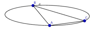
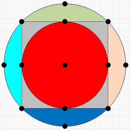
The principle behind it is a pair of laser lines, separated by a known, precise, angle and rotating at a rate (assumed to be constant only while in the short time it is sweeping the object) which then sweep a pair of sensors with a known separation.
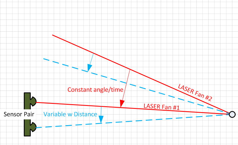
For a laser pair (L1 and L2) sweeping down around the horizontal axis, the time between laser L1 hitting the top and bottom sensor is a factor of how far the sensor pair is from the centre of rotation due to the constant rate and variable, relative, angle.
The time between laser fan L1 and L2 hitting the same sensor is always the same, regardless of distance, because the angle and the rate of rotation within the time-frame of the sweep are very constant. Taking the ratio of these two times will remove the rotational speed from the equation and give you a relative distance between the sensor pair and the lasers. Knowing the exact vertical separation between the sensors and also knowing the exact angle between the laser fans will fix the distance to a known scale.
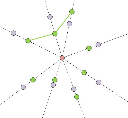
Many of these pairs, along with horizontal and vertical sweeping lasers, will give you the distance and orientation of the object cluster with respect to the base station.
COMPARING THIS APPROACH TO THE HTC VIVE SYNC PULSE:CONSTANT SPEED APPROACH
PROS:
- The lack of a "pulse" phase means the distances can be much greater.
- This approach does not need exact rotational speeds, only consistent speeds whilst sweeping over the object which makes the hardware easier/cheaper.
- Different rotational speeds (within bands) can be used to determine different bases and axis. This allows multiple bases sweeping without the need to sync them all together.
- As the only critical time for interference is limited to the time it is sweeping over the cluster, different rotational speeds for all the bases minimises the interference between them to very infrequent clashes. Then, on the next sweep following the clash, they have moved away from each other.
- Target movement, so long as it's linear whilst the laser sweeps the target, changes both the apparent speed of rotation as well as the duration between the hits. This essentially compensates for movement.
CONS:
- With a single base station you still have degrees of freedom in the position of the tracked object. It would need three base stations or two base stations and an IMU to give full pose. Interestingly, this goes away for tracked robots where the ground plane and the sensors height and orientation to that plane are known (i.e. ideal for factory tracking).
- Due to the fact that you only get relative angles between the detector positions, it's impossible to get a position without doing a full pose estimation. By contrast, the Pulse:Constant sweep approach rough angles can be estimated easily and, with triangulation, rough position too.
- Target movement, if fast enough, could make one base look like another if the apparent rotational speed change is great enough.


 Timescale
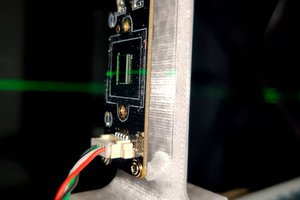
 Bryan Howard
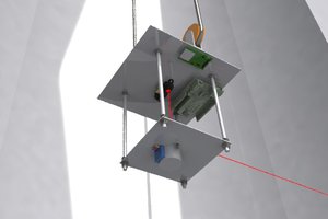
 Laio Athos Nevar Fonseca
 Supplyframe DesignLab
Good Desigm