Close
0%
0%

DIY fiber optic sensors, again

Make your own fiber optic sensors

Similar projects worth following
This project aims to describe repeatable way of producing simple and cheap fiber optic sensors, capable of measuring mechanical force, perhaps also other physical quantities.
Advantages of fiber optic sensors include high resistance to outer electromagnetic fields, also nonexistence of own electric influence, making them inherently spark safe.

What is this?

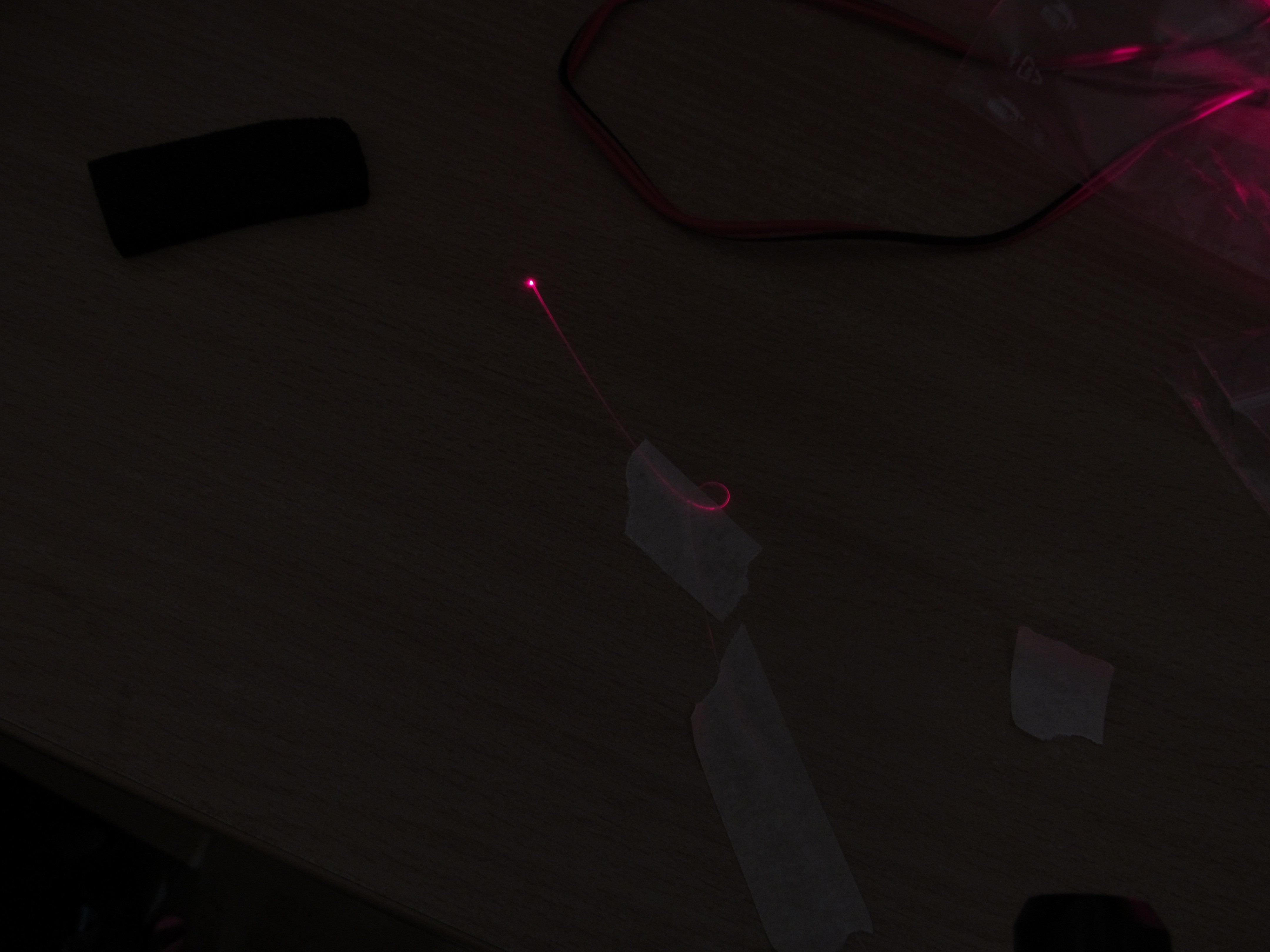
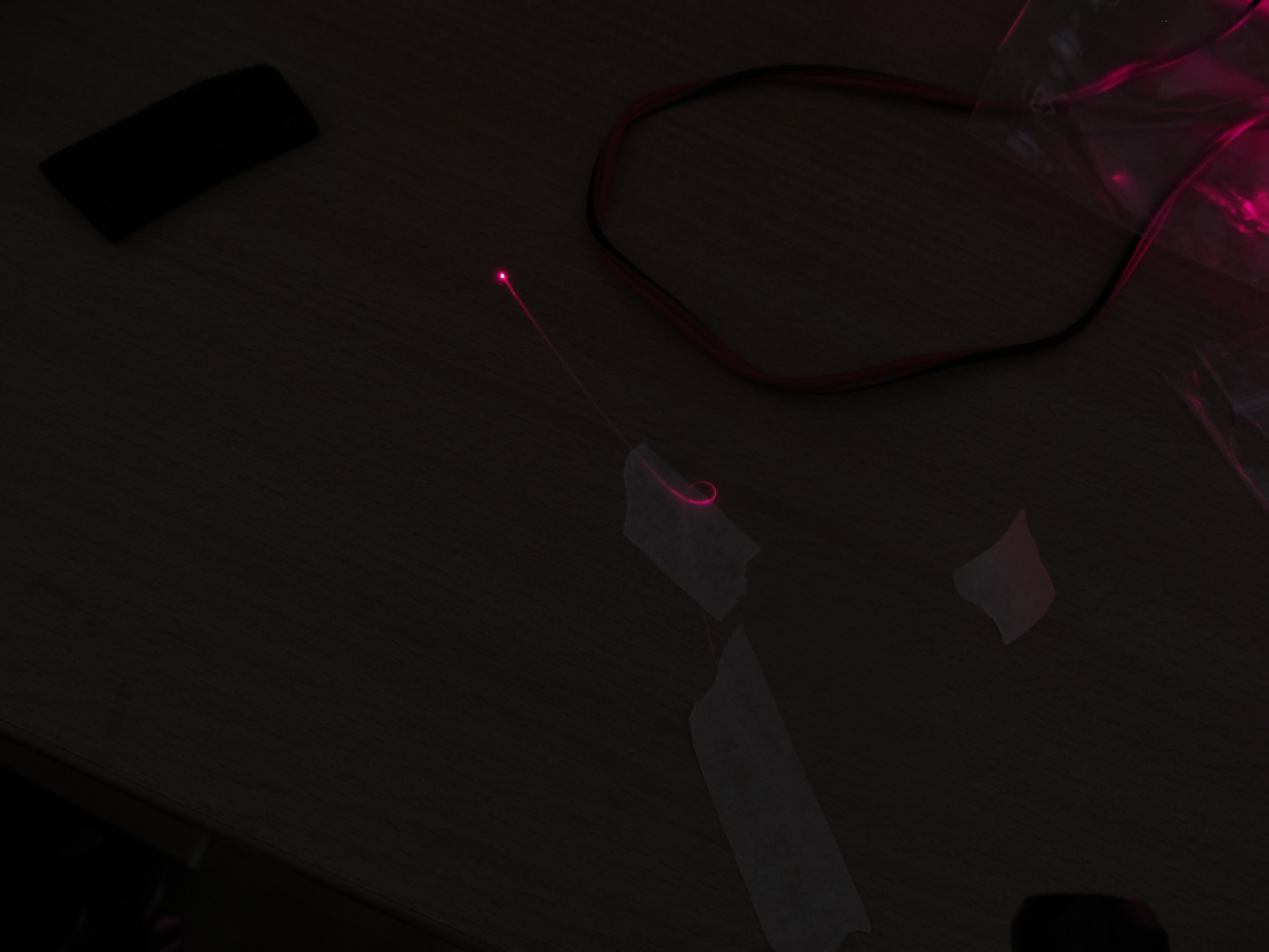
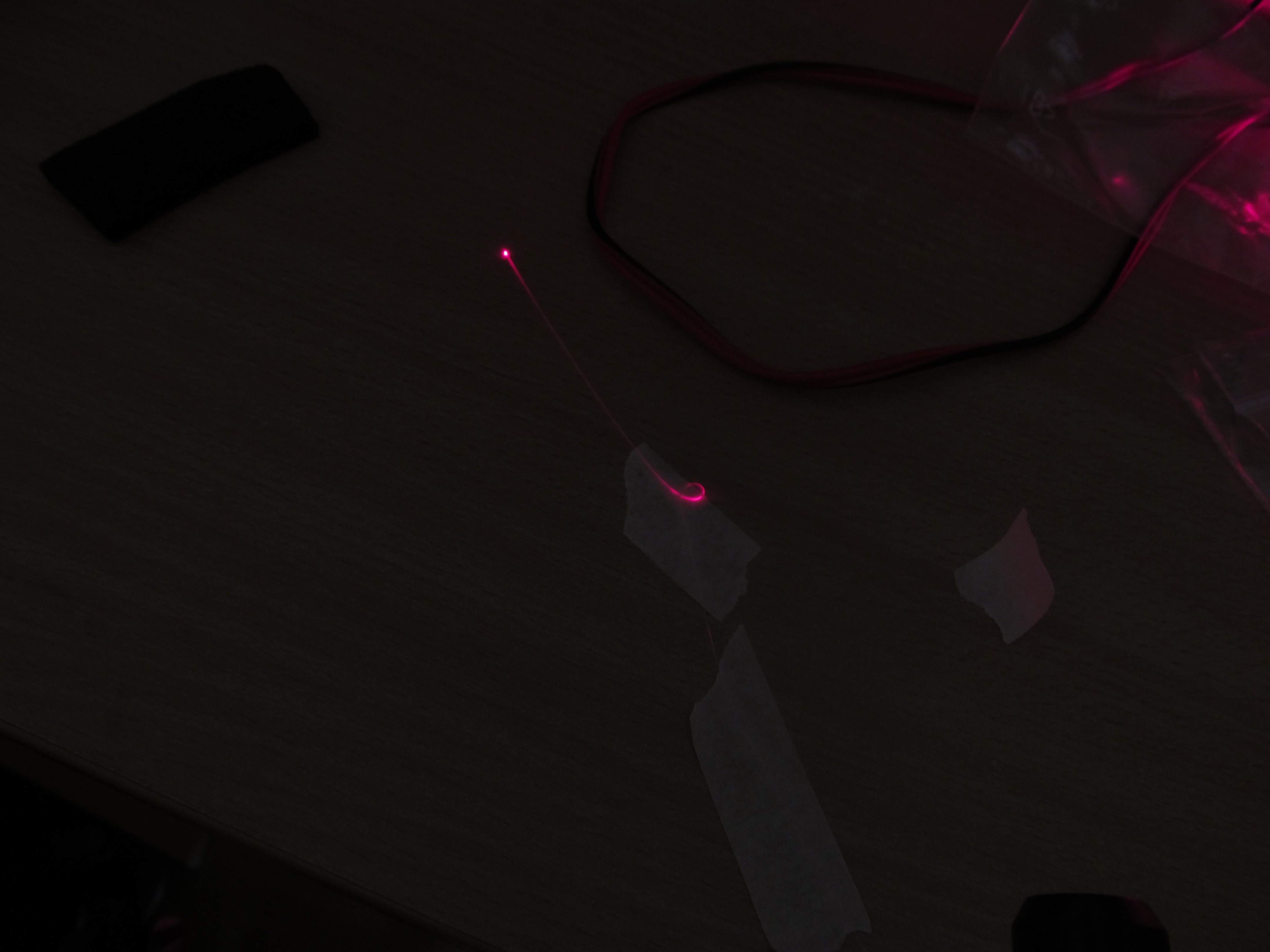
This is implementation of fiber optic sensors (FOS), ie. sensors where are no electronics at place, just optic fiber and some passive mechanical structures. FOS can be made to measure many physical quantities, like force, pressure, weight, temperature, vibrations.

Why bother, when we have electric sensors for this?

Electric sensors are great for a lot of applications, but there are environments, where those aren't usable - like measurement of temperature inside power transformer, strain on high voltage lines - and electric sensors would be upset by this conditions. Also, there are examples where voltage in those sensors - though not being particularly high - can be potentially dangerous for the environment, like danger of sparking around explosive materials.

But you need some electronics with FOS, right?

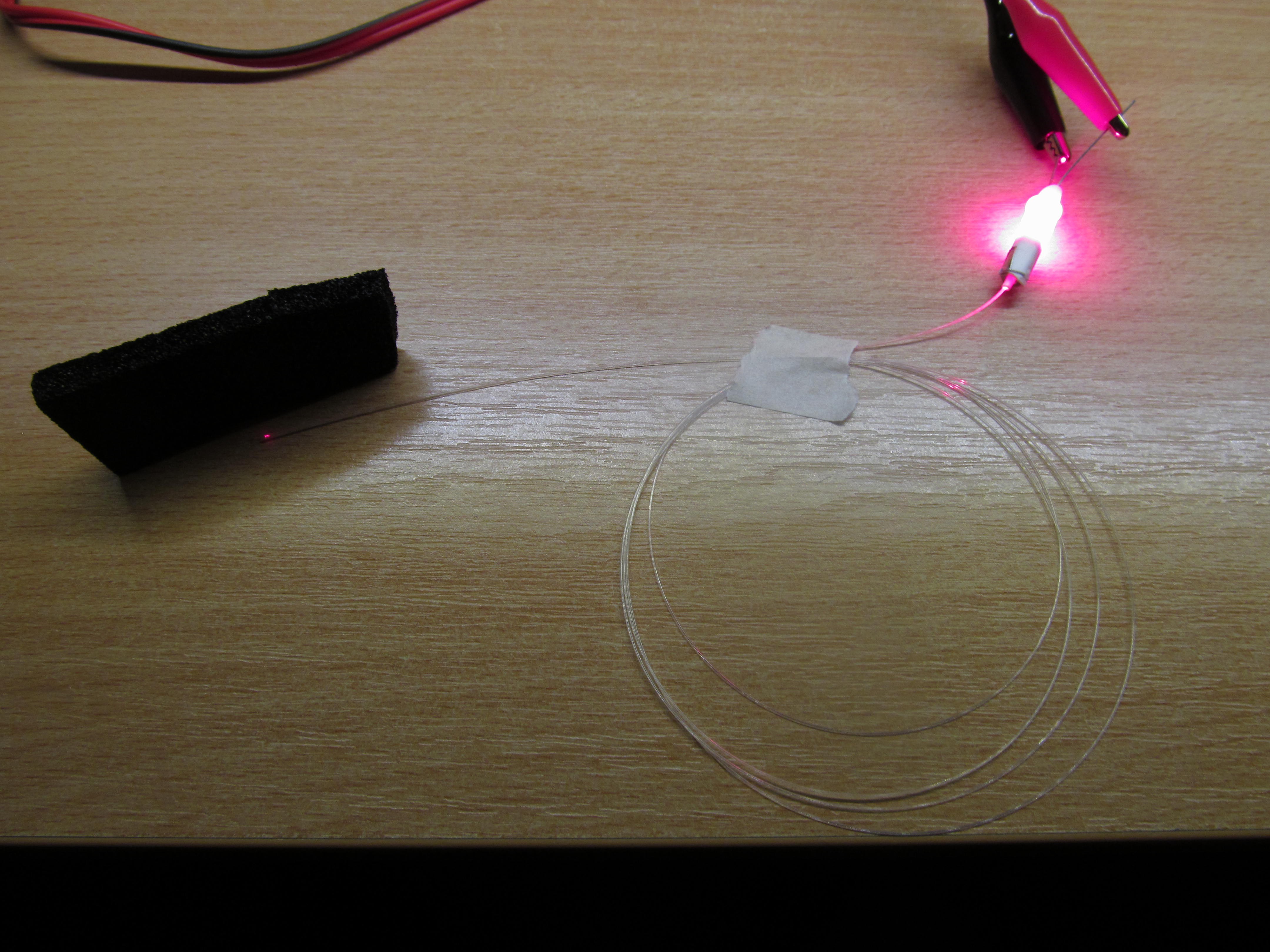
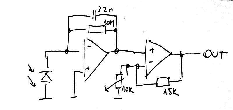
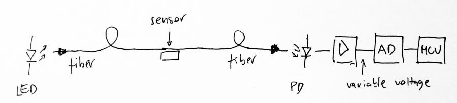
Yes, usually you need to emit some light into the fiber and also look at the sensors response, with photodiode, amplifiers, ADC etc. The point is that those could be fairly far away from measured point, with potentially hostile environment and signal is transferred by optic fiber.  This has also another implied advantage - the 'fairly far away' can be  like hundreds of meter, perhaps kilometers. In comparison with electronic sensors - there is usually problem to have electronic sensors that far away.

That looks complicated and expensive

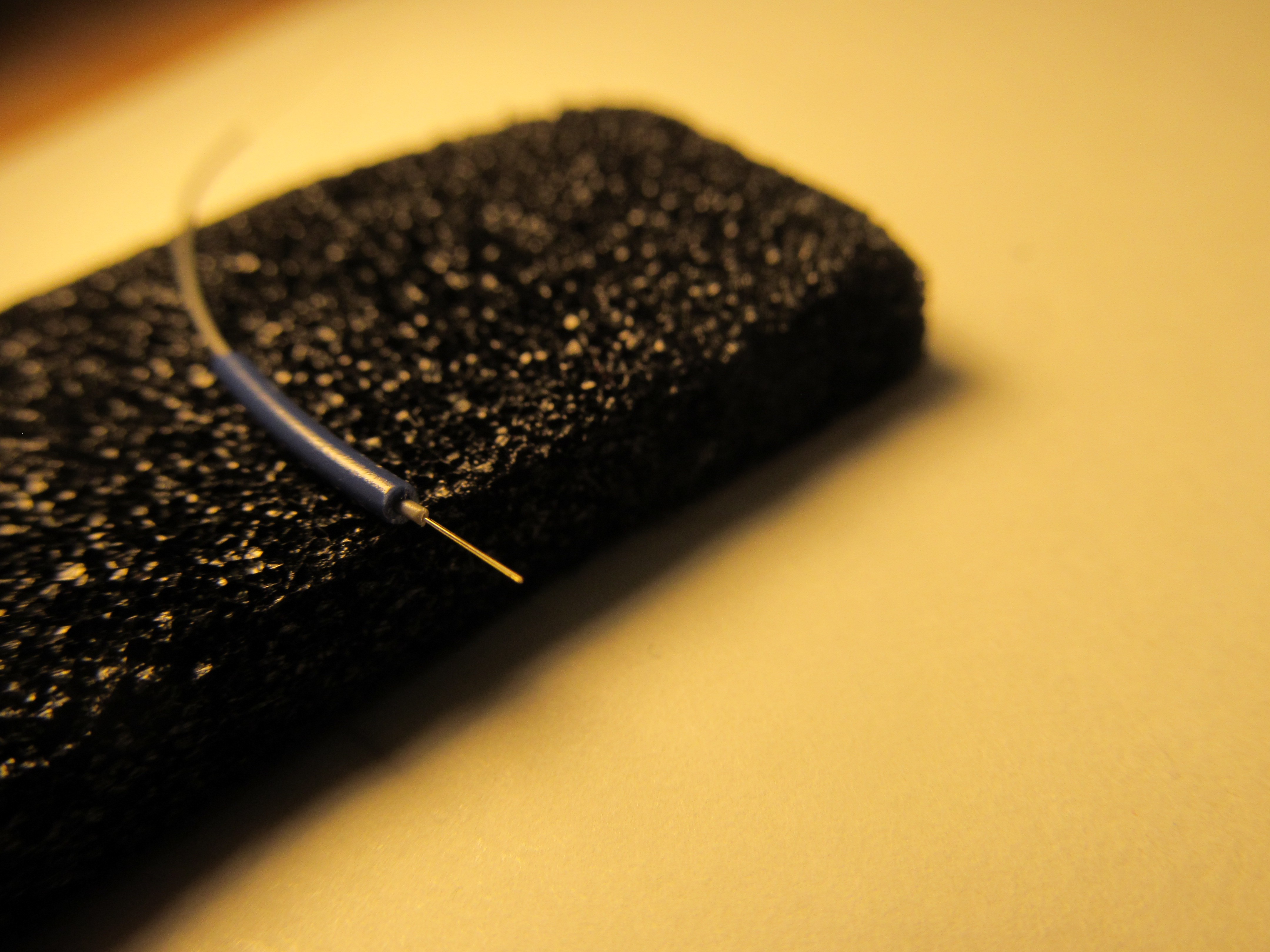
Not that much, really. Multimode fiber can be bought for 0,15E/m, or at local telecom company for free as waste material, the rest is just basic electronic components available at your usual supplier. Two channel sensor similar to what I did can be made for 5-10USD, if you use cheap arduino compatible board. No other special tools are needed. All my knowledge is here, sources are on github, I used FOSS to build this.

In comparison, professional FOS solutions are at price at least two orders of magnitude higher.

  • Few words about the software demo

    patex198704/23/2018 at 12:17 0 comments

    My contribution to this project was rather small - I was responsible for the visualisation software. It could have been written in various languages, but I like to be challenged, so I chose Python. I really like the community around it, lot of great data science tools are already packaged with core language.

    I used open-source libraries:

    • The GUI is built in TkInter. There is no graphical editor for the GUI, but it can be written with no more than 80 lines of code
    • The data visualization is done using matplotlib
    • Serial communication si done via PySerial

    The program can be run on Windows and Linux as well (no need to recompile, works without any headaches)

  • Résumé

    jaromir.sukuba04/22/2018 at 21:33 1 comment

    As the deadline for first round of hackaday prize is approaching, I feel like it's time to look back.

    I started this project with @patex1987 few days ago, with 50m roll of bare optical fiber, no special fiber optic tools, just a few back of the envelope sketches and common junk-bin component selection. By now we have three pieces of working fiber optics sensors.

    Some parameters, like stability, are yet to be improved, but this short experiment definitely shows potential in DIY building of this class of sensors for their appealing features, opening doors to cheap and available measurement of physical quantities in environments not common until now, as the environment would upset the electric sensors - like high current or voltage circuits, or in ionizing radiation. Also, in areas, where any electronics in sensors is not desirable, like in medical experiments, or around explosive gases. Those areas are domain of both expensive and proprietary industrial fiber optic sensors. While our experiment has room to improve to be compared to professional solution, I believe it shows promising way; being implemented with tools available to anybody in both hardware and firmware domains and completely open knowledge, it has door open to future growth.

  • Possible improvements

    jaromir.sukuba04/22/2018 at 21:06 1 comment

    I'm glad the first idea, followed by three prototypes of two designs worked as I envisioned, including possible problems. Both designs do need flexible material under the fiber - and this material should be really flexible and return to its previous shape after force is gone, Unfortunately, the pieces of black foam I used aren't the best in this characteristic and it somehow remembered its deformed shape. You can see it on this longer-term (roughly 6 minutes) graph

    Blue line is sensor response, I added red line showing how zero of this sensor drifted after full load test, slowly returned to original value, but never really got there. I'm pretty sure there are better flexible materials than random black foam I found in my drawer, perhaps latex or something.

    Also, I thought of different designs, like pressure sensor

    There are two fibers under reflective diaphragm, aligned so that light coming out of one fiber is reflected into second fiber. As pressure is applied to the diaphragm, it bends and light is deflected from its ideal path, so receiving fiber gets less light and dip in output light power is detected. As the light coming out of fiber is refracted, the slope of sensitivity (that will depend on clearance of fibers to diaphragm) will allow linear operation, at least in some region of pressures. Because fiber is not bent here, POF would be good candidate for such as application.

    Another design would utilize two fibers, aligned coaxially, with small air gap between them. If the fibers will be misaligned now, either by changing the angle to something other than 0 degrees (situation A on picture below) or offsetting them (situation B), losses in this device will increase again, easy to be measured. Funny how @Ted Yapo had the same idea.

    In both those designs, the measurement principle is not based on extreme bending of fiber, so cheaper and more common POF could be used here.

  • Sensors measurement, demonstration

    jaromir.sukuba04/22/2018 at 19:01 0 comments

    In previous project log I described how I designed two kinds of force/displacement sensors, now it's time to demonstrate how it's working.

    Amplifier board provides voltage, proportional to optical power on receiver photodiode; simplest way to determine the sensor output is hooking up voltmeter, like DMM set to voltage range. In order to allow transferring the measured values to computer, I could use any microcontroller with ADC and UART, there is plentiful choices and I opted to use MSP430 MCU, just because I wanted to entertain myself a bit by stepping outside of my Microchip routine.

    I had one MSP430F5529 launchpad accumulating dust for a while. I wrote single-file C program to exercise UART and ADC of this MCU, continuously measuring voltage on two ADC channels, waiting for user input and emitting the measured values once user sends expected string.

    @patex1987 wrote graphical demonstration program in Python, asking periodically the MSP430 for measured values, parsing the output, displaying both numerical and graphic output, as color gradient ranging from yellow (no load) to red (fully loaded sensor). Apart from that, measured values are emitted to log file, for later analyze.

    Sources for the programs are in github repository.

    Having the means to visualize and log sensor response, I was really curious how the sensors do perform - starting by all plastic sensor. I took a few bits of "heavy hardware" (mechanical engineers may scoff, but as electronic engineer, I'm used mostly to M2,5 and M3 screws), namely M10 spacers, each weighing 57g.

    I considered all of them being the same weight (acceptable for my rough characterization), so I ran measurement and logging while stacking them one by one

    Adding the weight manually caused a lot of wobble, but that made the characterization just slightly more complicated

    Red line is measured value from one sensor, going down as I added more weight; I put 6 pieces in total. Blue is slope of last 10 measurements, allowing me to find stable areas (where slope is near to zero). This boiled down to seven values from which I calculated rough "calibration data".

    The sensor response is surprisingly linear. I didn't dare to go further than 6 blocks (342g total), so let's call this maximal allowable load, or roughly 3,4N of force.

    I did the same for suspended sensor, though using smaller M6 spacers, each by 18g.

    The response wasn't that linear, but still quite good. This sensor is also much more sensitive than plastic one.

    I assume the culprit here may be friction of not exactly perfectly aligned linear bearing, as the first point is mostly off, other being OK-ish.

    In next log, I'll talk a bit of sensor stability and possible improvements of the design.

  • Sensor design, and method and apparatus for manufacturing same

    jaromir.sukuba04/21/2018 at 22:21 0 comments

    After having basic project decision made and verified, I designed two kinds of 3D printable sensors. The most vital parts of sensor are the ones I mentioned before - flexible material, fiber and pushing rod, but I also need body that keeps it together, keeps pushing rod perpendicular to fiber and returns it to "zero position".

    Flexible sensor

    I took an inspiration from loudspeaker suspension design (the wavy yellow part)

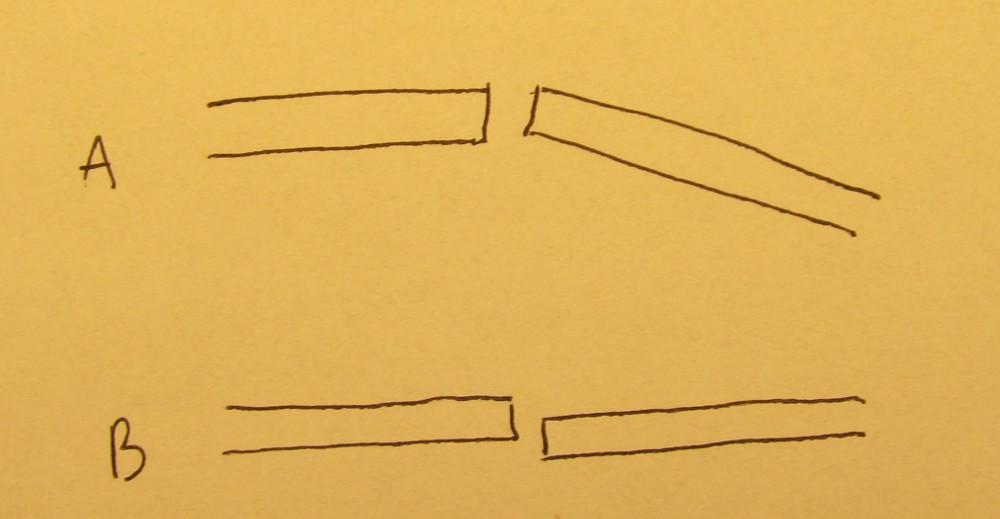
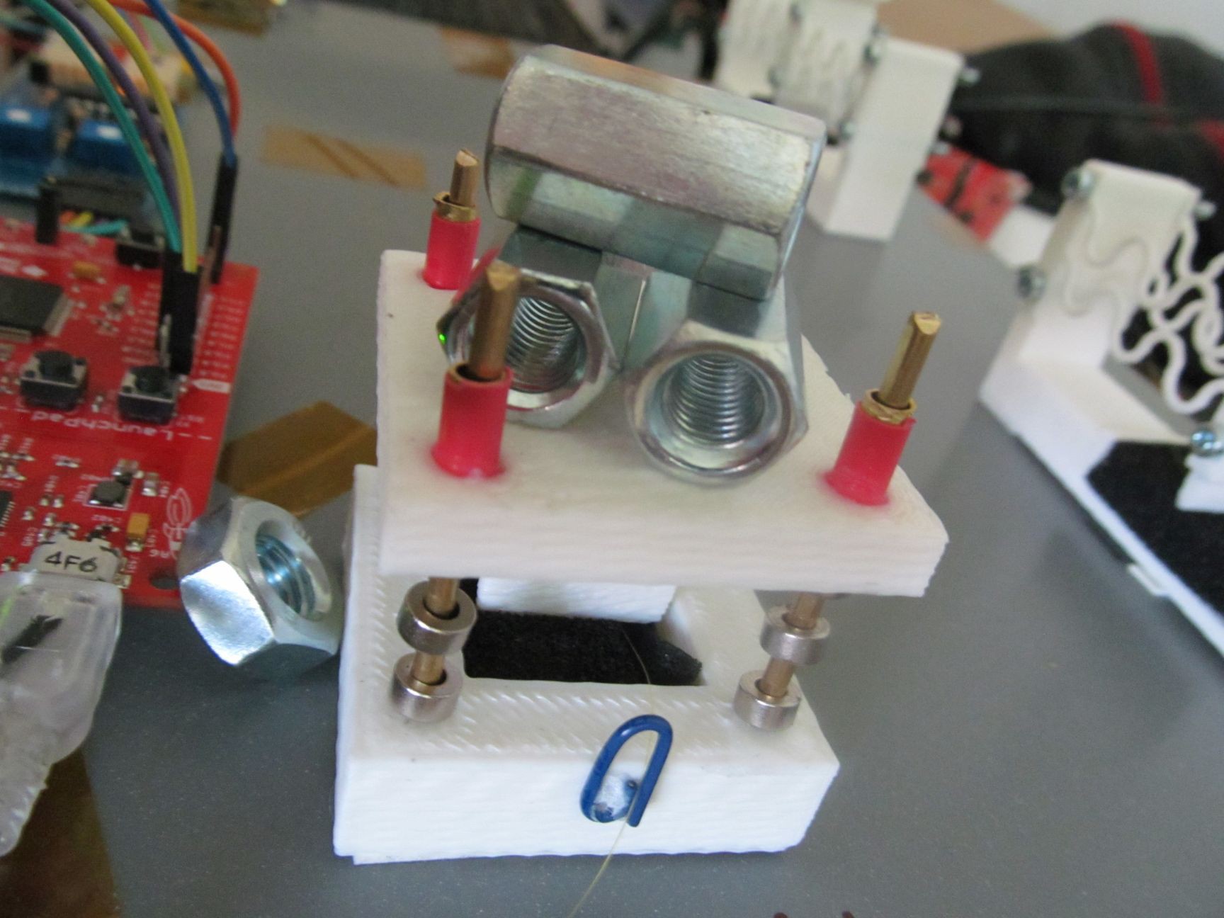
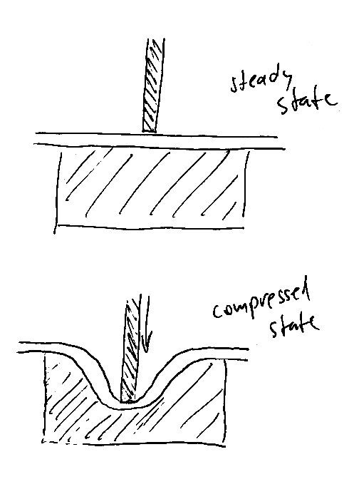
    This sensor takes advantage of flexibility of plastic to allow pushing rod movement.

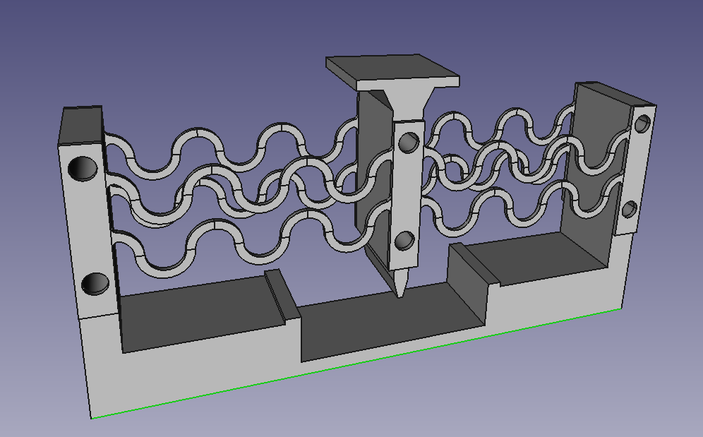
    or in slightly different view

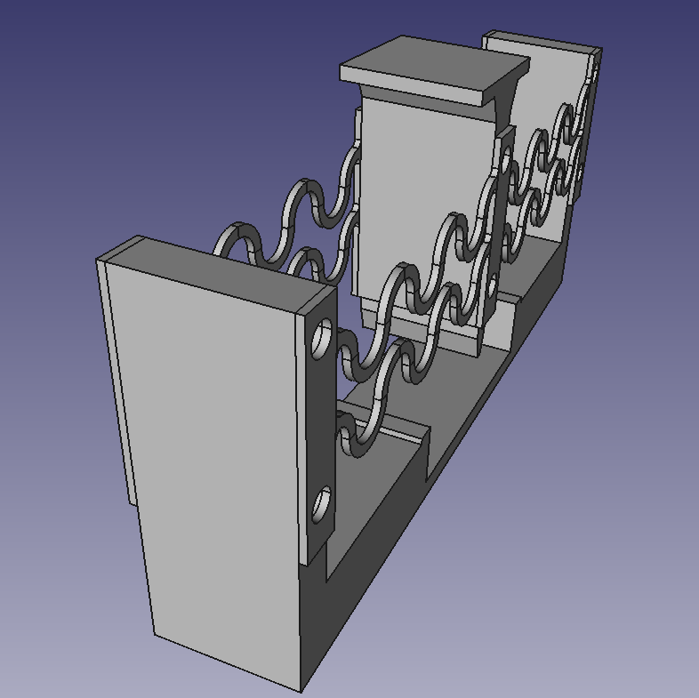
    It's made of three different kinds of 3D printed parts, in order to keep it simple and printable on average home printer.

    Suspended sensor
    Unlike first one, this doesn't use flexibility of plastic, but steel springs were planned as suspension. Sensor has smaller footprint and is smaller/faster to print.

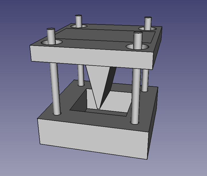
    Suspension is to be added on the four pillars, leading upper part with pushing rod against flexible material in empty space in bottom part.
    I realized this is good project to use magnetic springs - hollow magnets stacked on non-magnetic pillars, with alternating orientation to keep them repelling. I spent a minute playing with this toy

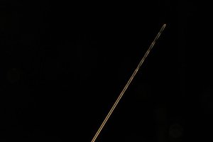
    I only had 2,5mm OD brass bar, because that was what I had available. The magnets do have 3,2mm ID, so 3mm bar would be better fit.

    As I was printing the sensor parts and assembling them, my desk was getting tangled messy heap of cables, fibers and tools, so I made project board by turning shelf container upside down, all items are tacked by double sided adhesive foam tape - because, well, this is hackaday.

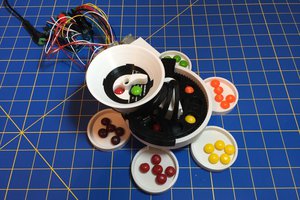
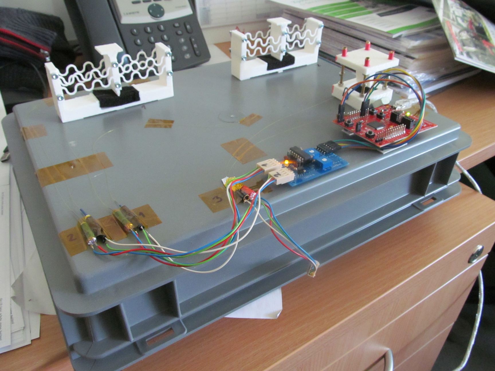
    Fibers and opto-electronic parts are secured by adhesive tape, so I can move this project with no worry of broken fibers. Detail of amplifier board and MSP430F5529 launchpad.

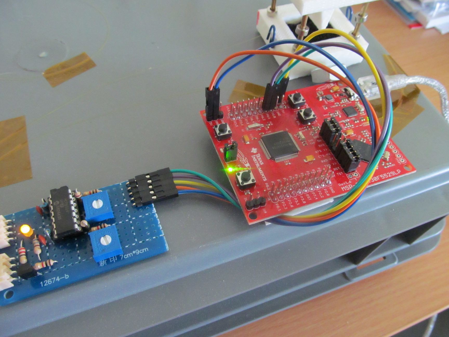
    I decided to use MSP430 just for the sake of exploring something new.

    Detailed view on flexible sensor with no load...

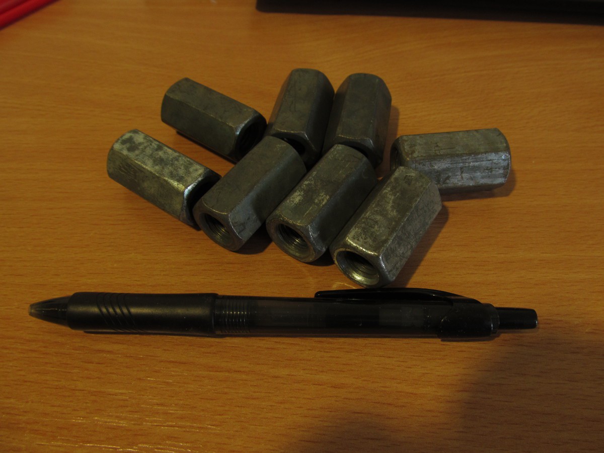
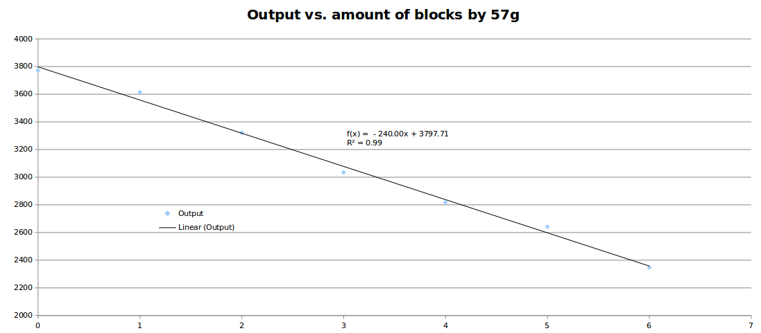
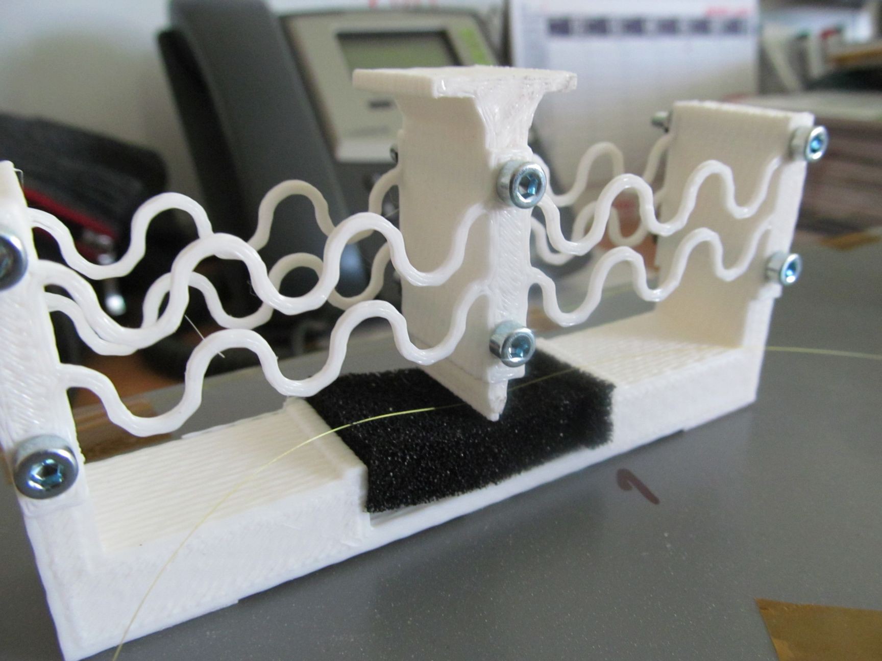
    ...and fully loaded (~400g)

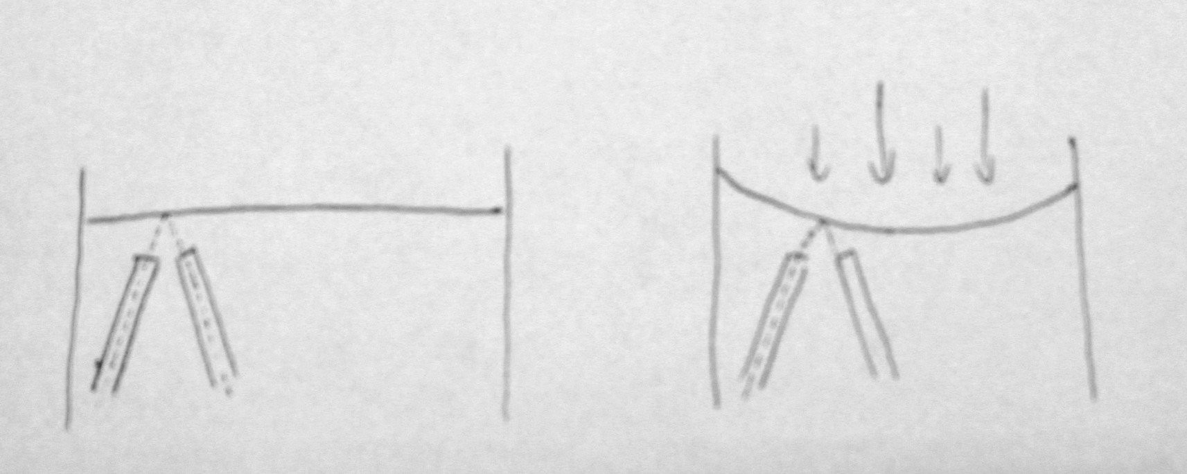
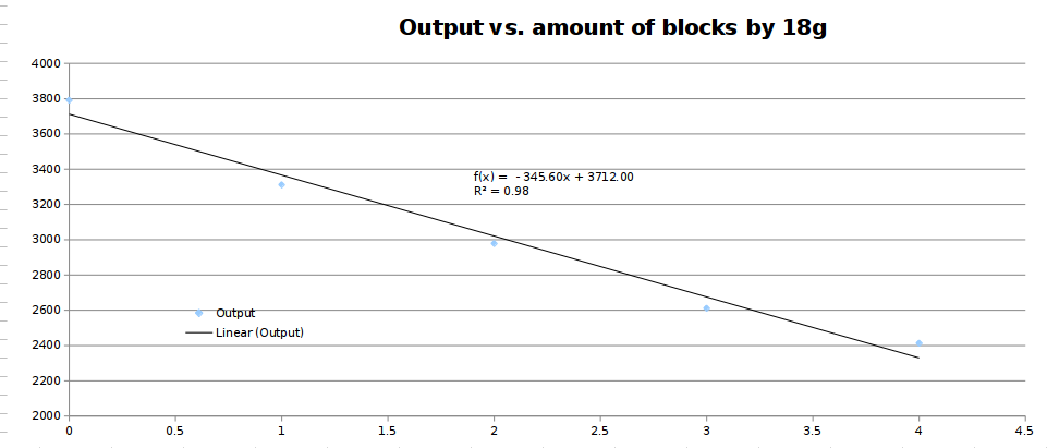
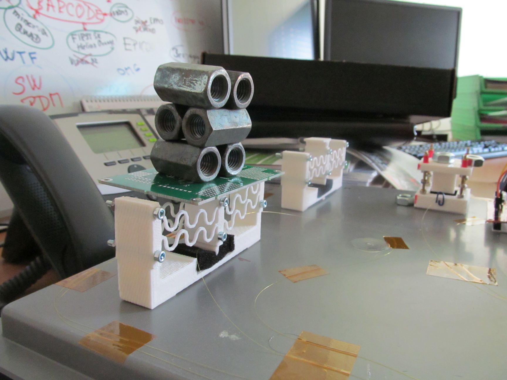
    The suspended sensor. was tortured, too. Only 50g for this one, though.

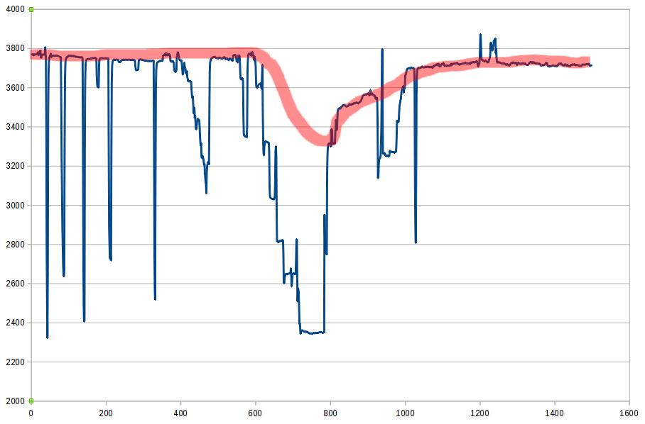
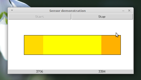
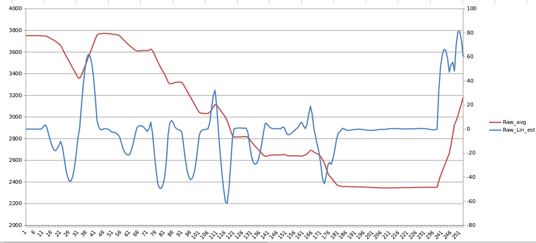
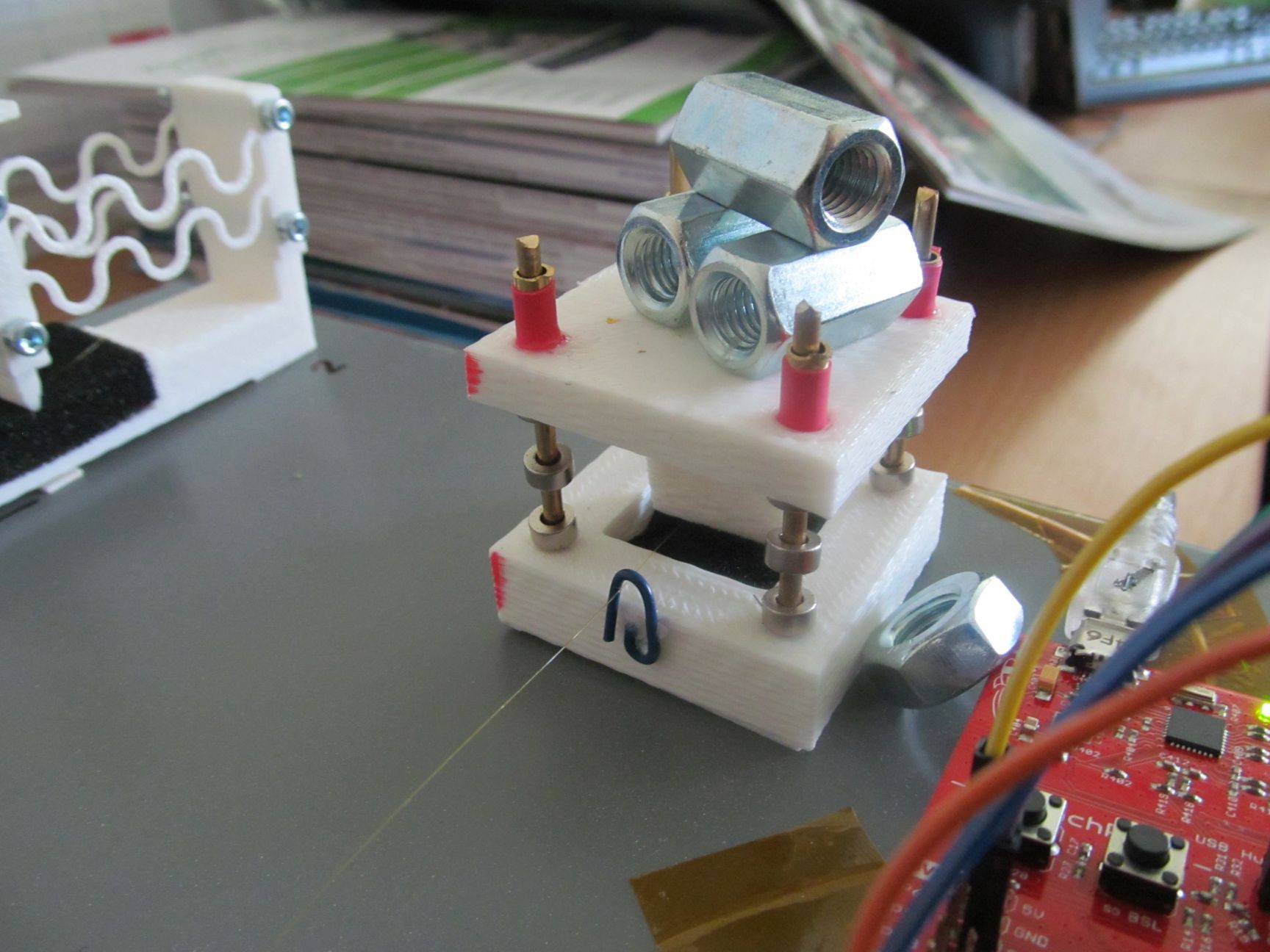
    No fiber optic sensors were harmed during making of this project. In future project log, I'll take a look at results and how I measured it.
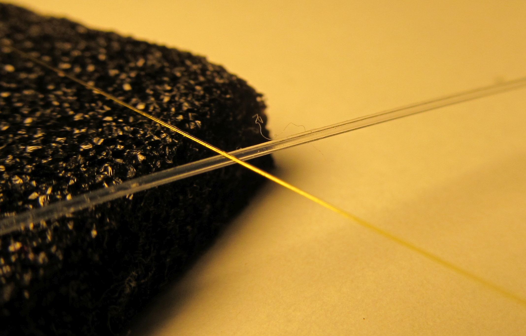
  • Practical experiments

    jaromir.sukuba04/21/2018 at 19:47 0 comments

    I managed to obtain two samples of fiber - first one is plastic optic fiber (POF) with outer diameter of 0,8mm. This is cheap OF used for home multimedia equipment. Another one is "proper" multimode telecommunication OF, with outer diameter of 250um and core diameter 50um. Here you can see both fibers:

    I started my experiments with POF, as it's easier to get some light into it.

    I took high-efficiency red LED and by simply holding the end of fiber in front of working LED, I got enough light to see bright red dot on other side of fiber. So, with help of heatshrink tube, piece of wire insulation and piece of metal tube (actually 10mm metal spacer) I made simple contraption to squeeze some light into POF.

    The light transfer efficiency is actually very low, I assume it's in order of few percent maximally, but it's both cheap and sufficient for quick and dirty project.

    Then, I made one turn on the fiber, to introduce some bend-induced loss. Notice how the bend leaks light meant to be kept inside the fiber.

    I tightened the bend - at the same exposure, bend is somehow brighter.

    I did some more tightening, the bend is even brighter now.

    The decrease of outcoming light isn't much visible on photos, despite the exposure time being the same for all three photos; dynamic range on those photographs is probably too high for my camera.

    After this foreplay with POF and visible light, I opted to use more common combination - IR light and multimode fiber. The core of fiber is much smaller than that of POF, so aiming the light from LED is not as much trivial as for POF. In professional applications, lasers and collimators/lenses are used, but making this in DIY somehow complicated; buying them is roughly one order of magnitude more expensive than this complete project - so I opted for absolutely barabaric approach; basically the same as for POF - placing open end of fiber in front of IR emitter and hoping for the best.

    In this case, 'the best' is coupling ratio at least two orders of magnitude worse than for POF. In order to point the fiber to the emitter somehow more precisely, I inserted the fiber into tubing pulled from 30AWG kapton wire-wrap wire and then again, inserted into another tubing from 0,6mm internal diameter single core wire.

    Anybody experienced in fiber optics is probably facepalming/sighing loudly now as this is really medieval. I know there are proper ways of doing fiber termination and coupling to light source, but it's really out of scope of this cheap/quick/simple project.

    I inserted the "wide end" of fiber into the metallic tube, touching IR emitter or end of tube and glued it in place with a dab of cyanoacrylate glue.

    So, having the fiber somehow coupled to light source, I did the same for photodiode on other side of fiber, forming emitter/receiver couple. I setup my laboratory power supply to source 100mA into IR emitter VSLY5850 and hooked up my most sensitive ammeter to photodiode, namely SFH203. Not surprisingly, short circuit of the photodiode was well under 1uA, somewhere around 50nA. It looks scary, but it isn't that horrible, with little help of opamps and transimpedance amplifiers. With very manageable feedback resistor of 10MOhm, I can get around half a volt on its output, that is easy to process. I took MCP6024 from my junkbox and did quick wiring of two TIAs, followed by voltage amplifiers for a good measure.

    This consumed all four opamps in MCP6024. I added 22nF capacitor in parallel with 10Mohm resistor to decrease bandwidth of the amplifier. It helps to minimize influence of 50Hz hum induced into photodiode circuit. It is possible to decrease its capacitance for higher bandwidth (=allowing to track faster changes of light intensity) if the circuit is electrostatically shielded. Trimmer in second stage allows to change gain (sensitivity) of receiver, I trimmed it to have 2,4V of full output, in order to fit the input range of particular ADC I used, as described in future project logs. Output of this amplifier is is now tracking...

    Read more »

  • How it works, first sketches

    jaromir.sukuba04/21/2018 at 18:33 3 comments

    The simplest way of making physical measurements with optical fiber (OF) is doing what you are usually explicitly being told to not to do - bending the fiber. It makes sense, as for proper fiber optic communication one is aiming at lowest possible loss of signal in OF; but that is not the case with fiber sensing applications. Here, we are looking for some way of modulating the passing light with the measured quantity, usually in form of amplitude, spectral or phase modulation. The easiest way is amplitude modulation (performed by bending the OF), so that's what I've chosen here.

    Bend the fiber!

    I will not repeat basics principles behind optical fibers as those are well known, I'll rather focus focus on the less usual aspects of this problematic.

    Key parameter of OF is insertion loss - ie. how much of light is attenuated by some amount of length, usually expressed in dB per km. This value is guaranteed by manufacturer, under specific conditions, one of them is bend radius. As bend radius decreases, light in OF core is can't follow the curvature and gets leaked to the fiber cladding, from which it can't enter to the core again and gets attenuated. The smaller bend radius, the more leak to cladding and higher insertion loss. One has to be careful here, as too tight bend can damage or even break the OF.

    Provided I can transform the measured quantity into OF bend and measure the insertion loss, I get fiber fiber optic sensor (FOS).

    One of possible arrangements is on picture below

    OF is placed on compressible material and movable push rod is placed above it. When push rod is pushed into compressible material, it bends the fiber and causes insertion loss. Within some limits, the insertion loss rises as push rod compresses the material; after saturation point (material is compressed, OF can't bend any more) it doesn't change much. The movement of push rod can mean measurement of position or displacement; with help of flexible material it can be transformed to force or weight measurement, or even air/fluid pressure (using flexible bellow) or temperature (with bimetal strip); or whatever else that can be converted to linear motion.

    Signal conditioning is not very complicated here.

    Led with appropriate wavelength emits light into the fiber, the light gets received with photodiode (PD in this block diagram). The amount of light (=signal from photodiode) is the higher the less attenuation is in path. Electric signal from photodiode is amplified by and ready for processing, in this example is brought to ADC and processed by microcontroller.

    As usual, devil is in detail, but that is something for next project log.

View all 7 project logs

Enjoy this project?

Share

Discussions

Similar Projects

Does this project spark your interest?

Become a member to follow this project and never miss any updates