 James Gibbard
The Goal
Build an assistive device that provides a sense of depth perception, via a haptic interface, to a user with a visual impairment in order to provide them with better situational awareness than is available from existing assistive devices.
To be deemed a success the final system must:
- Provide better situational awareness to the user that existing assistive devices, either when used on its own, or in combination with existing assistive devices (like a white cane).
- Operate stand-alone without tethered power or external processing.
- Operate both indoors and outdoors.
- Last at least 20 hours without recharging or switching batteries.
- Weigh less than 500 g.
- Cost less that £150 per device to manufacture in small quantities.
The Plan
Sensor
Initially the idea was to utilise a low cost radar module such as the K-LC5_V3 from RF Beam Microwave in order to detect depth. However, the basic non-pulsed operation of these radar modules would have made the signal processing for this application excessively complex since there would be multiple static and mobile objects within the field of view of the device.
Two further options would be to use a laser range finder or an ultrasonic distance sensor. However, both these sensors have a narrow field of view and can typically only resolve the distance of one object at a time. This would require the user to constantly move their head to gain situational awareness and smaller obstructions may be missed.
Lidar would be ideally suited to this application, but despite self driving cars continuously driving down the cost, it is still too expensive and cumbersome.
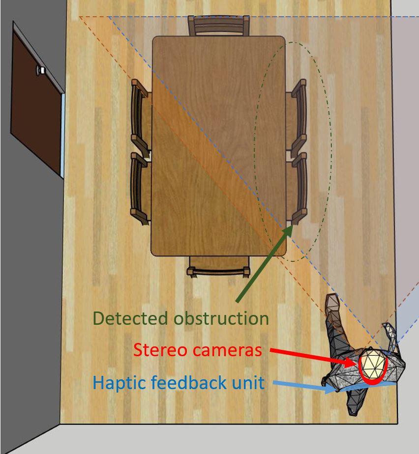
Using two cameras offset slightly from each other (stereo cameras) allows for distance information to be resolved in the same way in which our eyes work. The signal processing required to do this can be complex, but it is a well researched area with plenty of information available online via published papers as well as examples in open source libraries like OpenCV. Additionally the resolution and accuracy requirements in this project are likely to be much lower than most typical applications of stereo cameras as the human-machine interface will be the limiting factor in the information that can be presented to the user. This means simpler, lower performance algorithms can be used. Cameras can be purchased for under £5 and the algorithms to do the depth calculations can be accelerated using a processor aimed at performing DSP, or potentially using an FPGA. One further benefit of using a camera based system is that it leaves open the possibility of performing image recognition to detect features of interest to the user, for example a pedestrian road crossing.
Human computer interface
While an obvious choice would be an audio based interface, this would likely become annoying with extended use. Additionally people with visual impairments can gain significant situational awareness through listening to ambient sounds. Disrupting this would likely lead to a worse situational awareness even if the depth sensing system worked perfectly.
A better option is to use haptic feedback in the form of vibration to alert the user to the presence of obstructions. To be useful the system must allow for providing directional information on where the obstructions are as well as the approximate distance. Additionally the feedback provided to the user should be adapted based on the scenario; for example, if the user is not moving but facing a wall the device should not continuously vibrate warning the user that the wall is there.
We anticipate the majority of the engineering effort to go into designing the human-computer interface.
Stage 1 - Proof of concept
The first stage is all about proving the concept works, getting the team up to speed with the required technologies, and researching the best way to go about the project.
There are a large number of questions we need to answer before continuing to Stage 2. These include, but are not limited to:
- What resolution cameras do we need for this application?
- What rate do we need to update the depth information for acceptable results?
- What latency between input and output is acceptable to the user?
- Where should the "vibration actuators" be placed on the body?
- How many different "vibration actuators" can a user uniquely tell apart?
- How sensitive are users to the variance in vibration? What resolution can we provide the information at?
- How many vibration patterns can a user uniquely tell apart?
No effort will be made in stage one to optimise the design. The idea is to fail fast. If we can't do the required signal processing on a desktop PC, with an i7 processor, we are really going to struggle to do it on a low power embedded system. If users only have limited ability to sense vibrations then this sort of interface might not be able to provide information to the user with enough resolution to be useful. Discovering these types of issues during stage one gives plenty of time to switch approaches if required.
Stage 2 - Prototype
The second stage is all about moving towards a prototype that operates un-tethered under its only power. This means cumbersome webcams and desktops computers will have to be replaced with custom hardware and optimised software. During stage two optimising size, weight and power (SWAP) becomes the main challenge. The goal is to complete stage two before the end of the 2018 Hackaday Prize.
Stage 3 - Final design
This is a high risk experimental project so there's every chance we won't make it to stage 3, but if we do then it is all about going from a prototype to a product. Design for manufacturing becomes a priority. To meet the target cost both the BOM and manufacturing costs will have to be minimised. Finding reliable sources for all the parts is essential; i.e. if an obscure camera module, sourced off alibaba, was used in stage 2 it might no longer be an option for stage 3. Any regulatory conformance testing will be conducted in this stage.
The Team
Ashley
Ashley is an Electronics Engineer with a background in Physics and Mathematics. He has over 5 years experience working in research and development. His main skill set includes embedded development, circuit design, and RF testing/measurement.
James
James is an Electronics Engineer with 4 years experience working in research and development. His main skill set includes software defined radio, signal processing, and FPGA development.
Open Source
Regardless of whether the project works or not we want the hardware and software to be available to as many people as possible. Maybe someone else will see something we missed, or perhaps someone will be able to reuse parts of the project for a completely different purpose. We will use the MIT Licence on all hardware and software we create within the project. Where existing open source code or hardware is modified we will abide by the licence of that hardware or software.