 aerospark
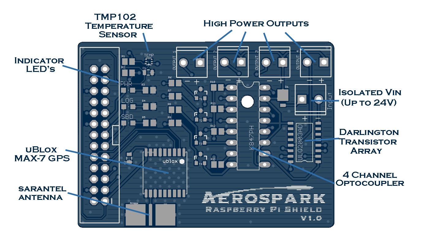
Figure 1: Aerospark Raspberry Pi Shield
In order to have reliable real-time tracking for our payload, there needs to be a better GPS onboard other than the one inside the RockBLOCK unit. The Iridium unit can estimate position, however it is way to inaccurate to be used for HAB (~10km off when I tested it).
The uBlox-MAX series has been used by HAB enthusiasts for several years and is rated for up to 50km altitude I ultimately decided to go with the newer uBlox MAX-7 for the PCB because it boasted improved accuracy of +/- 2m, and the MAX-6 we used last summer worked great. The Sarantel antenna makes the whole unit nice and compact, without the need of hanging external wires.
I threw some LED's in as well just to make it easy for testing/debugging as well as making sure everything is in working order before launch. The PWR LED will be on when the program is running, the LOG LED blinks every time data is logged to the Raspberry Pi's SD card, and the SBD LED will blink every time there is an SBD request to the Iridium Satellite Network.
The temperature sensor was added in to provide some more useful data to the users dashboard. It will be very useful if temperature sensitive equipment is placed inside the payload, and the user would like to heat the payload remotely from the website. For example, I will probably trigger a payload heater until I see the payload go back to near zero right before launching the rocket.
The rest of the circuit is for the optoisolator circuits. These were added to isolate any devices that may require higher power, without using the main battery or damaging the Pi. Personally, I will be using them for the ignition of a rocket, an optional cable cut down (for mission abort), deploying a parachute, and heating the payload. Some other ideas could be to power high power servos for a suborbital glider, etc. The circuit uses a 4 channel optocoupler with a darlington transistor array rated up to 24V. So if you use all four circuits are once and have 24V going into the input terminal, each output will get 24V/4 = 6V, or you could use one at a time to get the full voltage.
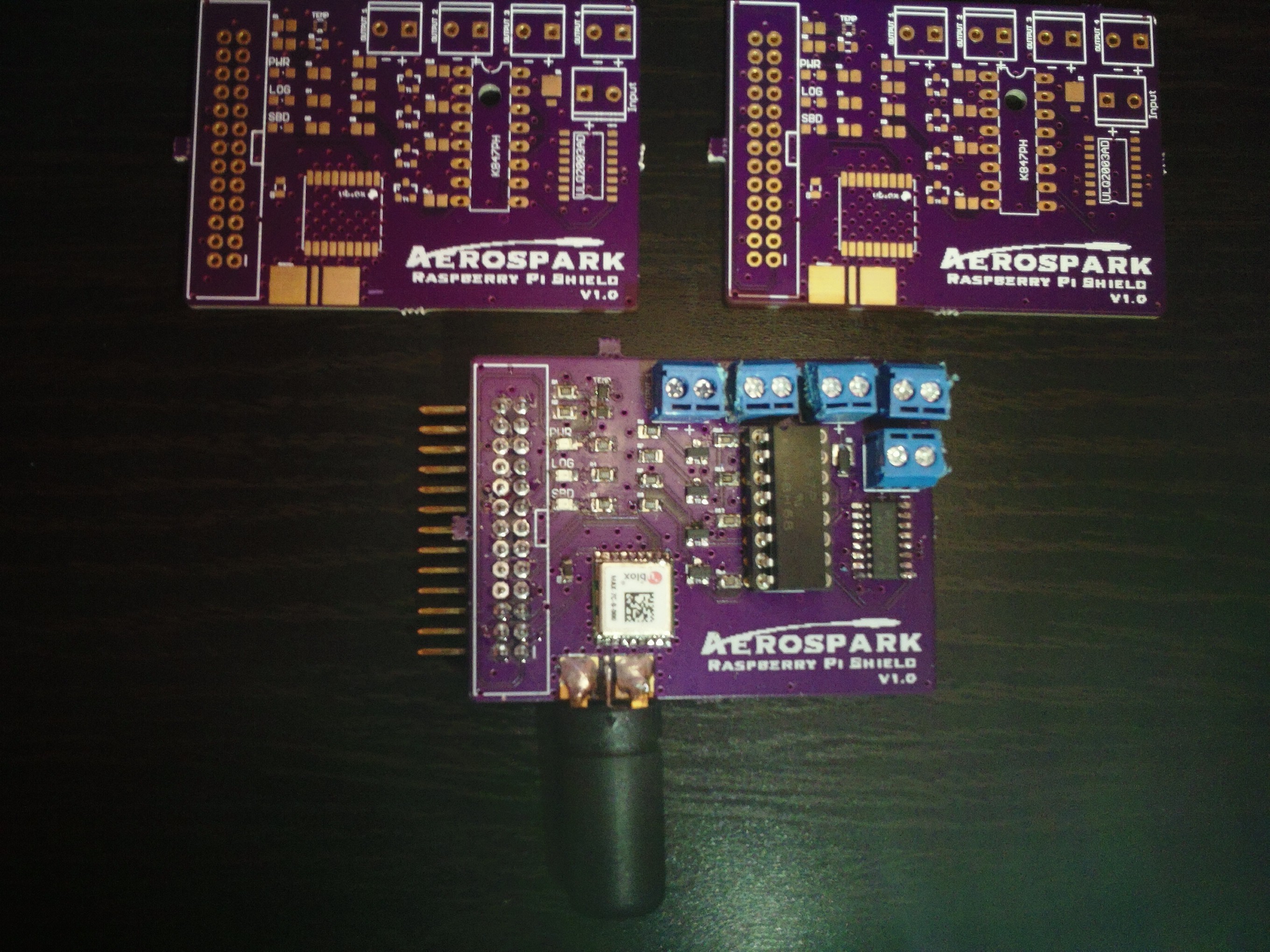
Figure 2: Manufactured PCBs
The circuit was designed using EagleCAD, and sent to OSH Park for manufacturing which took about 3 weeks to arrive. All components were purchased from element14 except for the uBlox and antenna. I had to pay quite a bit for those components because they were shipped from the UK, but the guy who runs the store was very helpful and even gave me some tips on the PCB design, thanks Anthony. On that note, I should also thank all the people on #highaltitude and #hackvana who gave me some tips on the PCB as well. I probably did atleast 3 full redesigns until all the feedback I got was satisfied.
The soldering was a bit of a challenge because I had never soldered SMD before. Originally I had hoped to use a reflow skillet, but I couldn't find the solder paste at any store and the people who worked at the stores all looked confused when I told them what I was looking for. Eventually, I decided to bite the bullet and just try hand soldering it. The TMP102 was fun, but I think it turned out alright (minus hacking away the wrong size terminals). Now for the testing...
Discussions
Become a Hackaday.io Member
Create an account to leave a comment. Already have an account? Log In.