 Jenny List
This is a project of two parts, the oscillator itself and its power supply. It involves high voltages, so if you are not sure what you are doing with such things then you might be better served avoiding it. BUILD THIS PROJECT AT YOUR OWN RISK.
The 2N3904 requires a high voltage to operate in avalanche mode, well over 100V. [Kerry] uses a Linear Technology switcher and a diode multiplier, but I did not have a suitable similar chip to hand and required instant gratification. I thus hacked together a PSU from junkbox parts.
It's a simple enough flyback design, a two-transistor flip-flop driving a high voltage switching transistor that switches the primary of a small transformer. The secondary voltage is rectified and smoothed with a capacitor.
The multivibrator is very simple indeed, with the components shown it runs at about 5kHz.
The switching transistor can be any high voltage switcher you'd find in a TV line output or on the mains side of a switch-mode PSU. I used a BU807 line-output transistor because I had one to hand, but if you're butchering an ATX PSU then one of its HV switchers would do just as well. It simply has to be able to take the flyback voltage from the transformer primary.
The transformer I used was the base drive transformer from an ATX PSU. One side of these transformers has a high turn count, this became my secondary. You will probably have to experiment with a few transformers, and maybe with different winding arrangements before you settle on the one that works best. The diode is a fast HV rectifier that came from the mains side of the same ATX PSU, almost any diode that can handle a few hundred volts should work here.
Finally the smoothing capacitor was part of the ATX PSU mains-side filter network. This capacitor needs to be able to handle a few hundred volts DC.
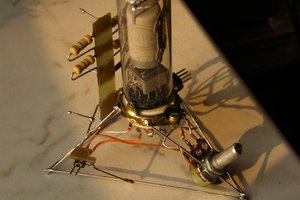
The oscillator is very simple, and follows [Kerry Wong]'s design closely. It is very important to keep all leads as short as possible here, as longer lead lengths will lengthen the pulse rise time. Mine is mounted right on the back of my BNC socket, and the whole circuit is placed dead-bug style on the copper baseplane of a surplus PCB from a prototype run.
In operation, it's important to keep an eye on the high voltage end of the circuit. The flyback inverter's voltage where the capacitor meets the diode depends on the input voltage, and if you wind it up it will produce about 300V maximum. BE VERY CAREFUL HERE, you risk damaging the circuit. Put it on a variable supply and start from zero, advancing the input voltage until you detect the oscillator starting with your oscilloscope. [Kerry] reported his one oscillating at about 120V, mine starts at about 150V which I get for an input voltage of about 2.5V. Once it's oscillating, I get pulses with an amplitude of about 70V, so be sure your 'scope input is at the right setting to take that.
You can see the resulting waveform as measured on my 'scope, it manages to resolve a 1.4nS rise time from the ~500pS pulse.
 DeepSOIC
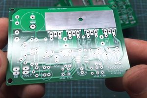
 Electroniclovers123

 electronicsworkshops