 Andy Osusky
Track the Boat
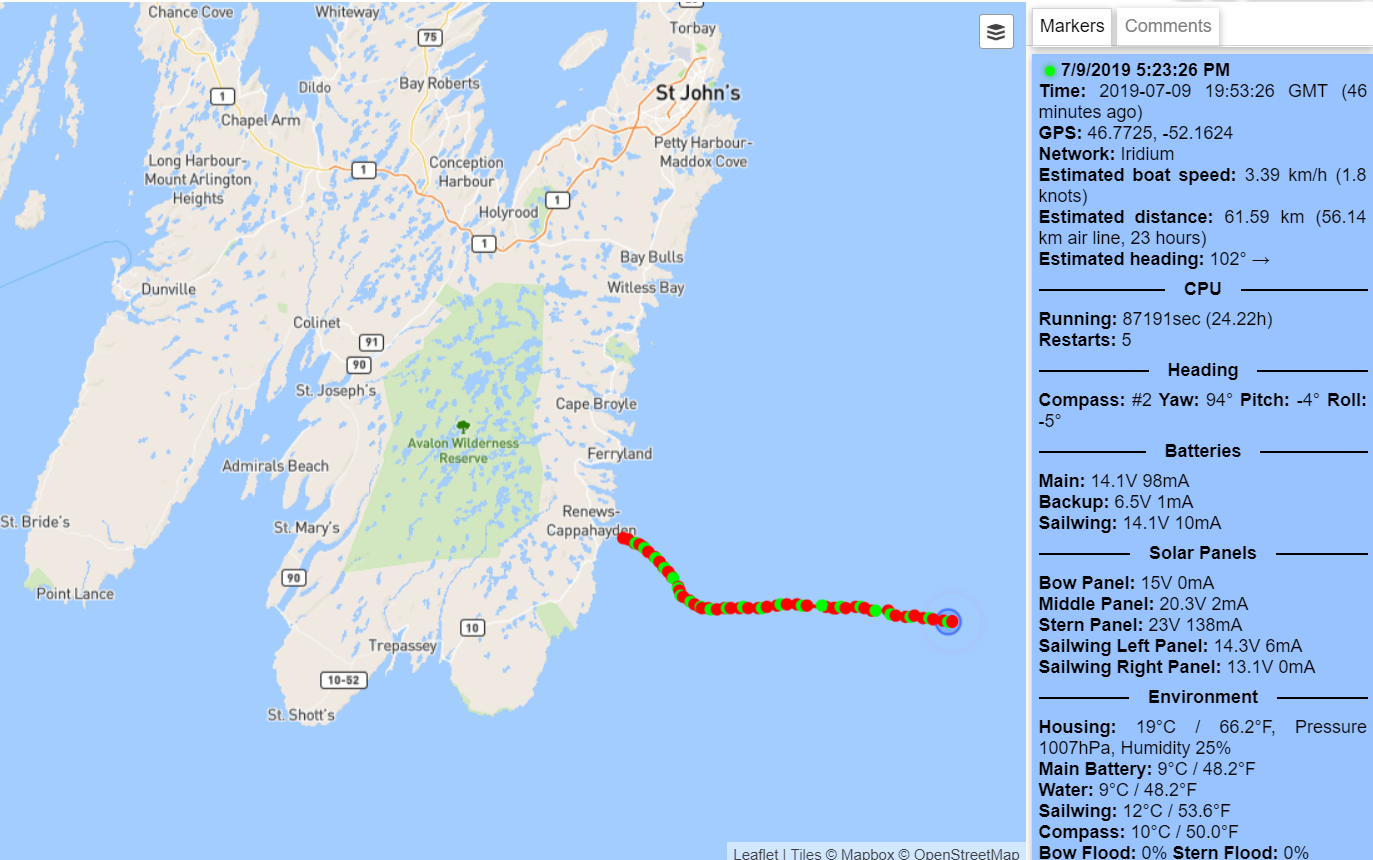
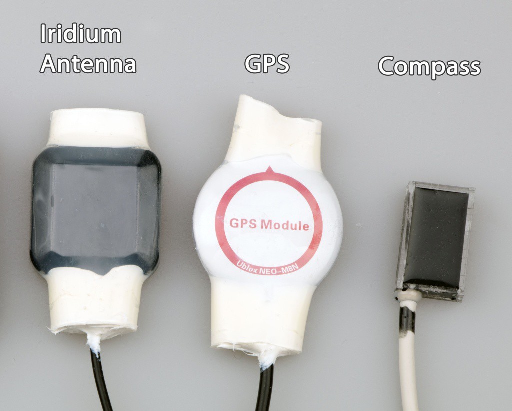
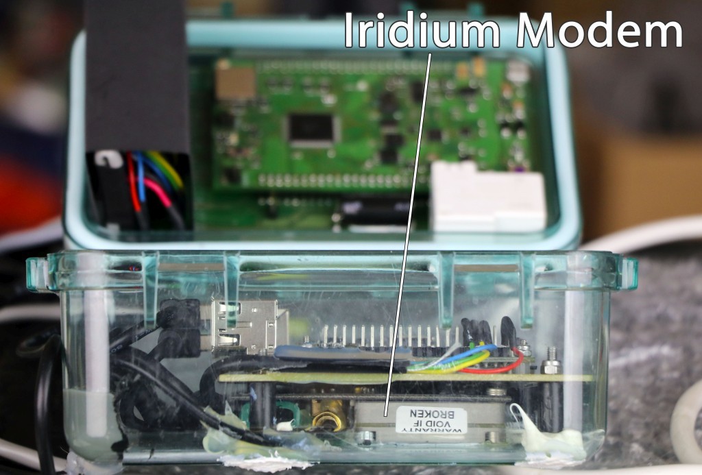
The boat reports its position and other interesting environmental data through the Iridium satellite network. You can track it here:
https://track.opentransat.com

Launched from Newfoundland
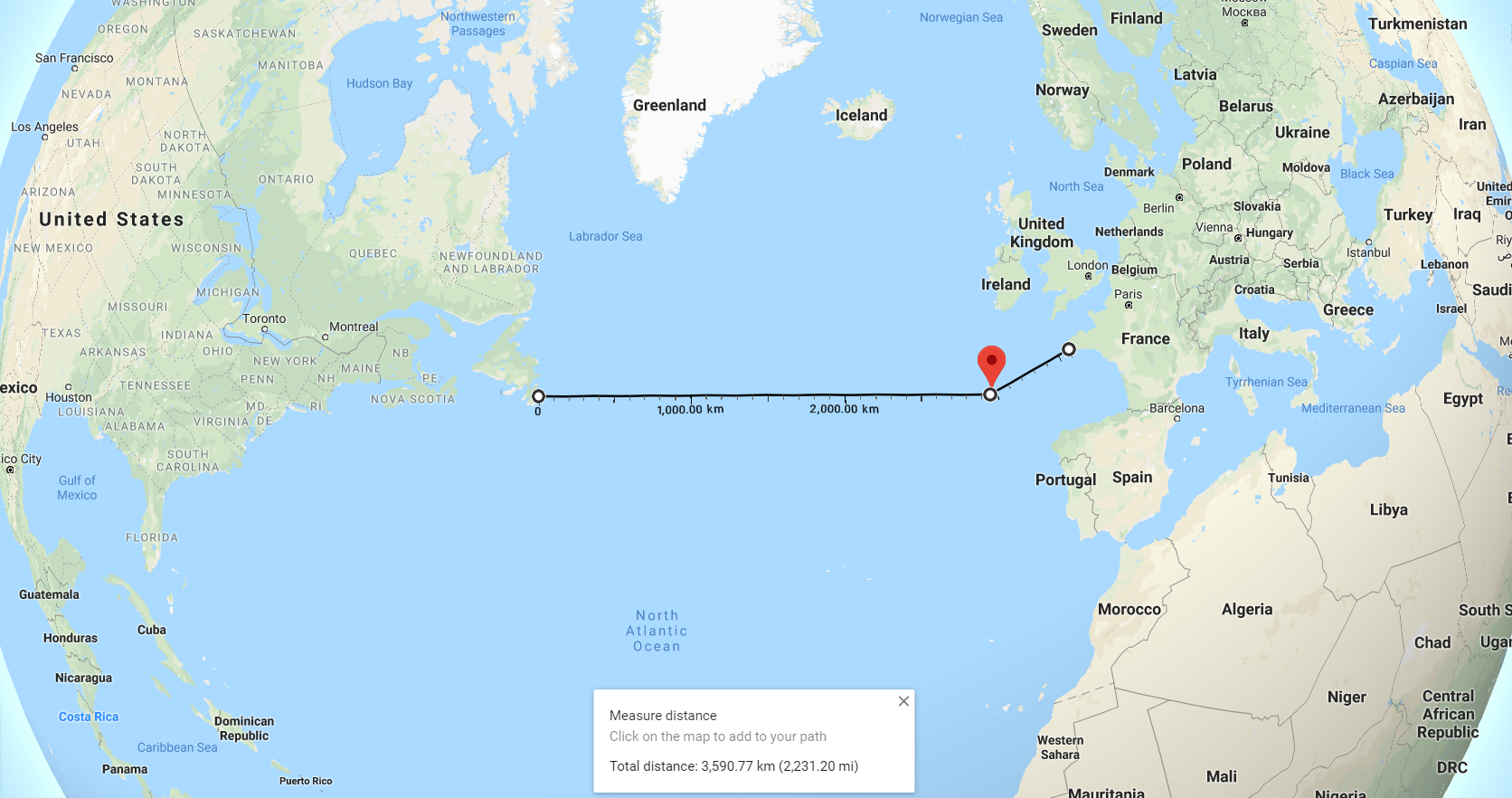
The boat was shipped to Newfoundland, Canada in several packages and launched from a fishing boat. The route across the Atlantic is defined by waypoints located on the start and finish line. When the boat gets within a certain radius of a waypoint, it continues to the next one. The challenge is considered completed when the boat hits the finish point #3. From there, it would continue sailing to France.
How It Works
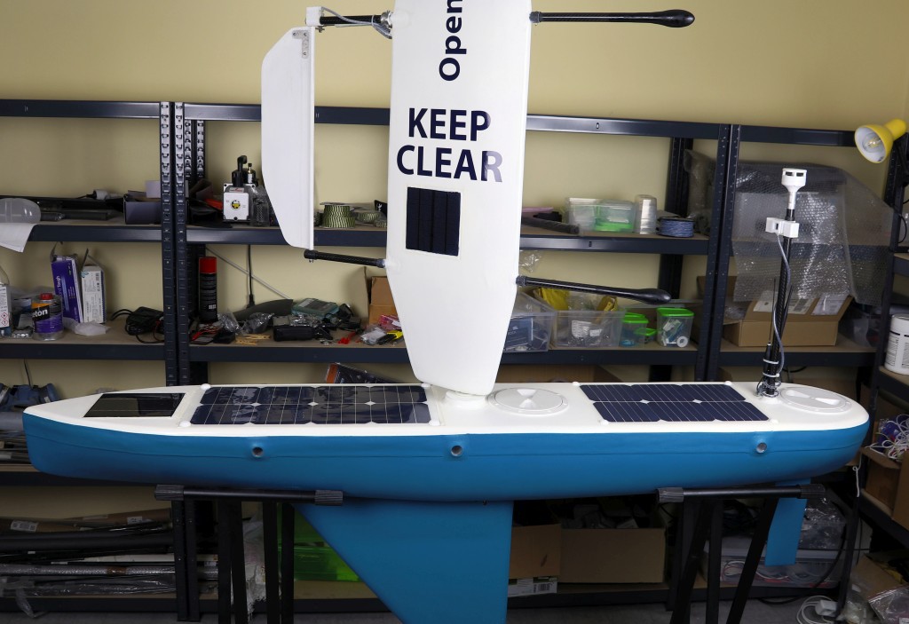
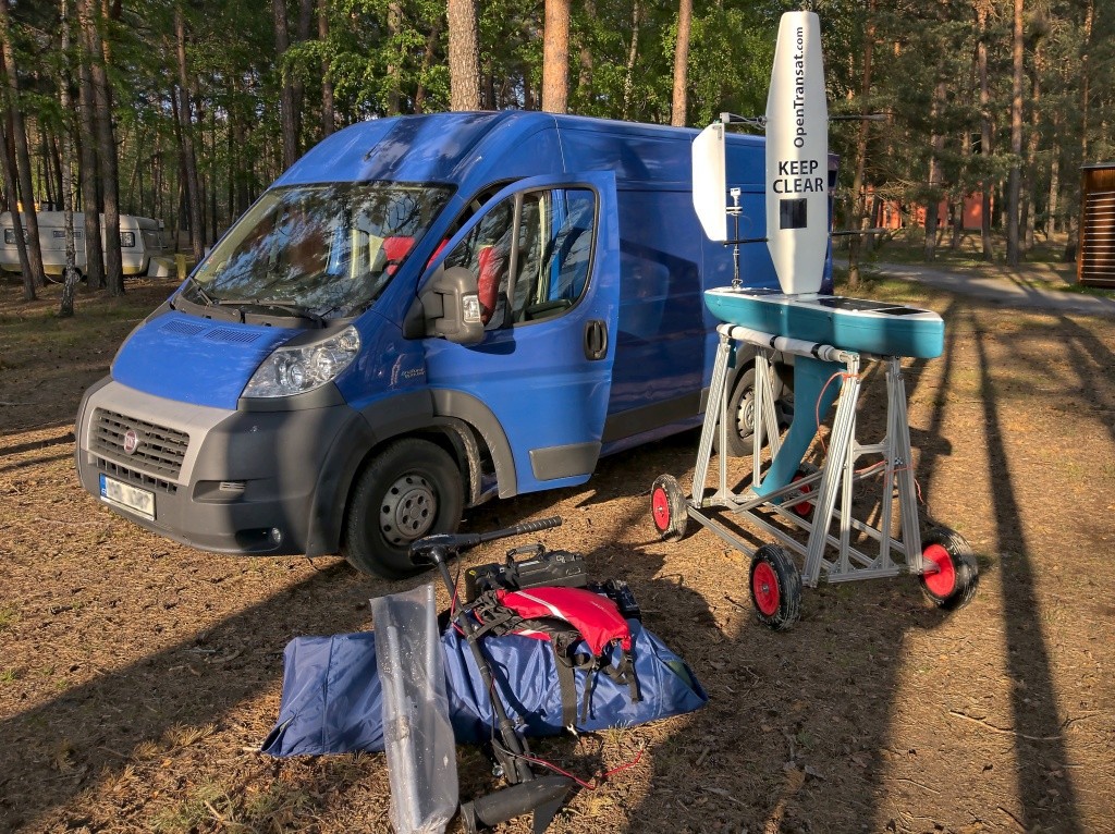
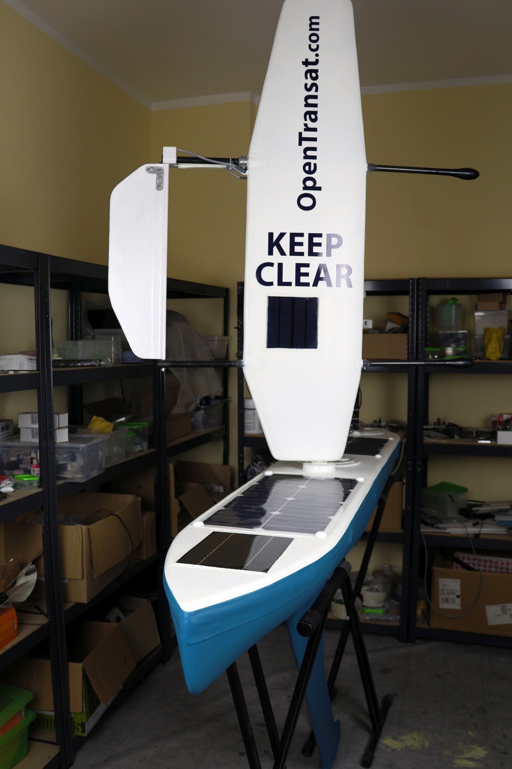
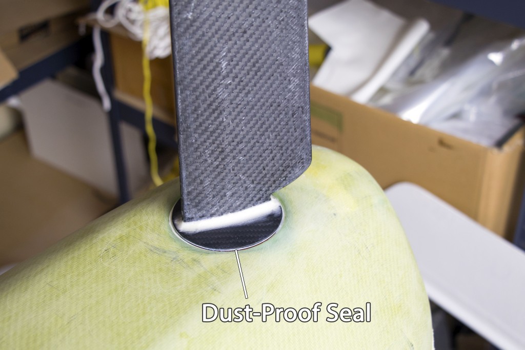
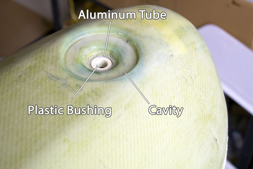
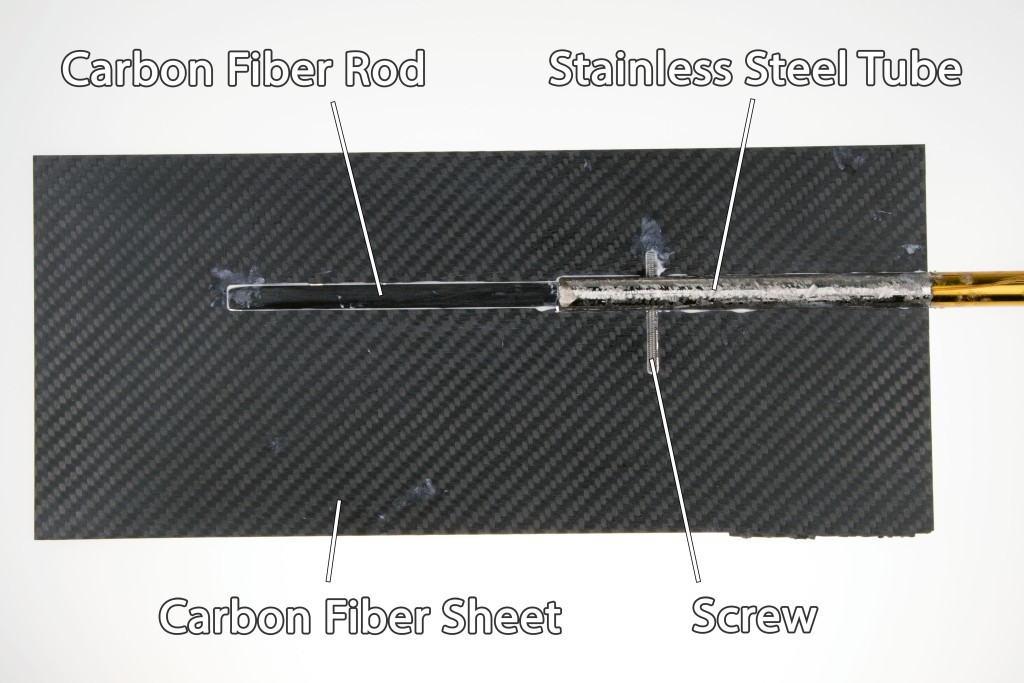
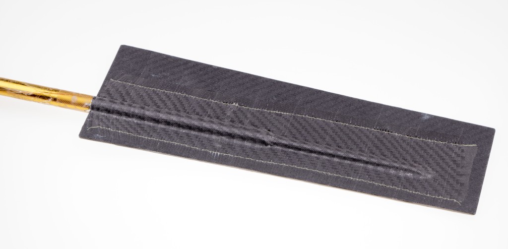
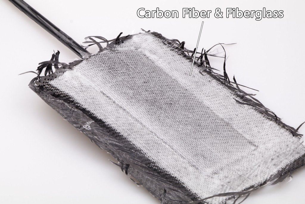
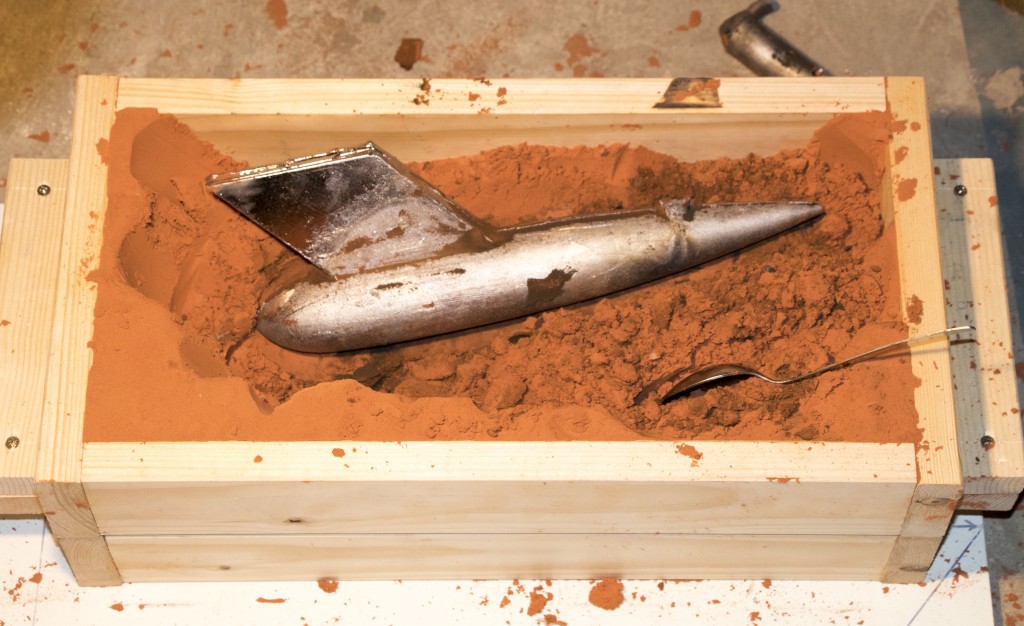
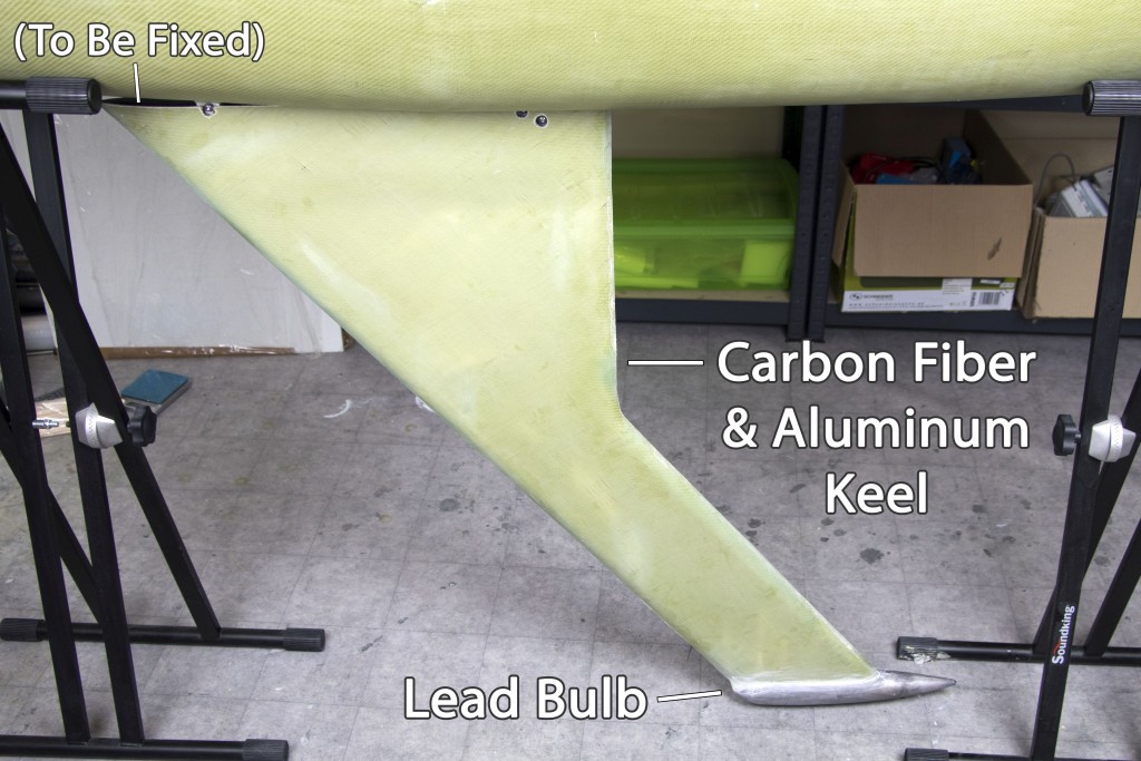
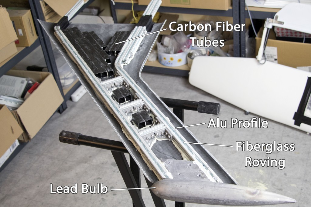
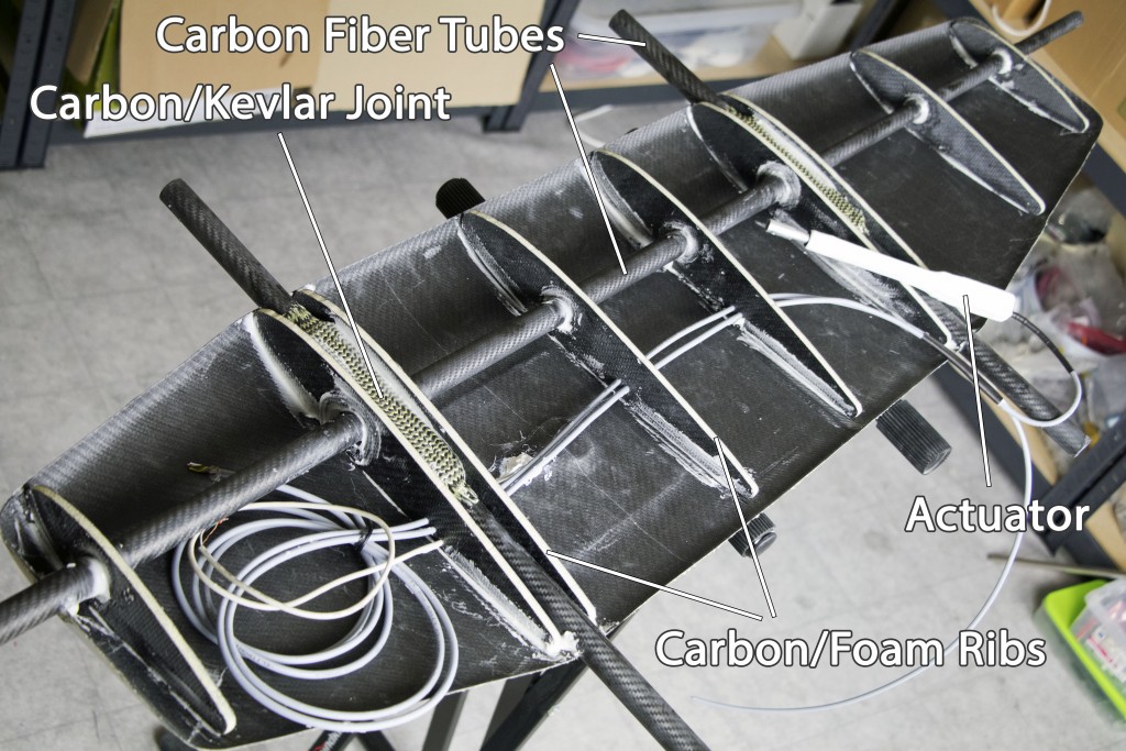
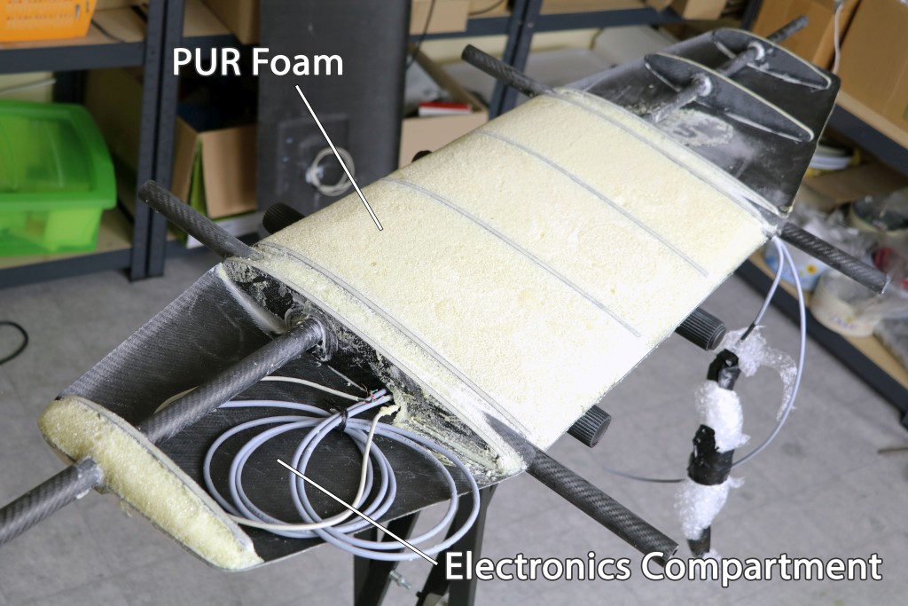
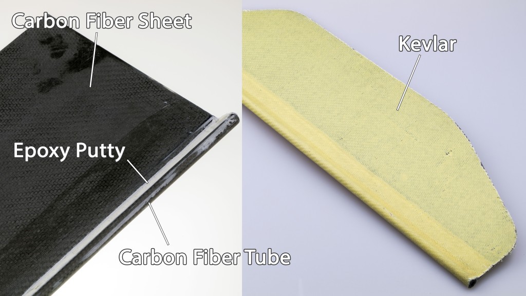
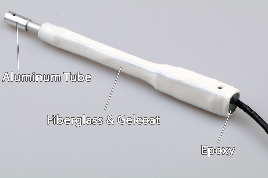
The newest boat is made from custom composite parts: carbon fiber, Kevlar, fiberglass and a foam core reinforced by aluminum / carbon-fiber skeleton.
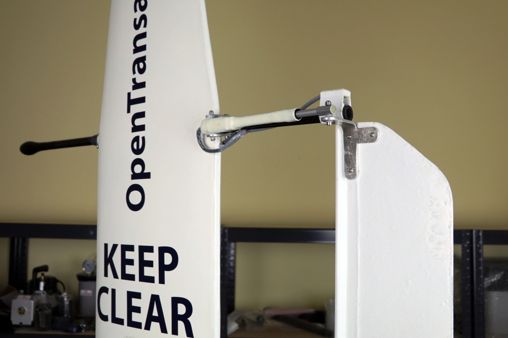
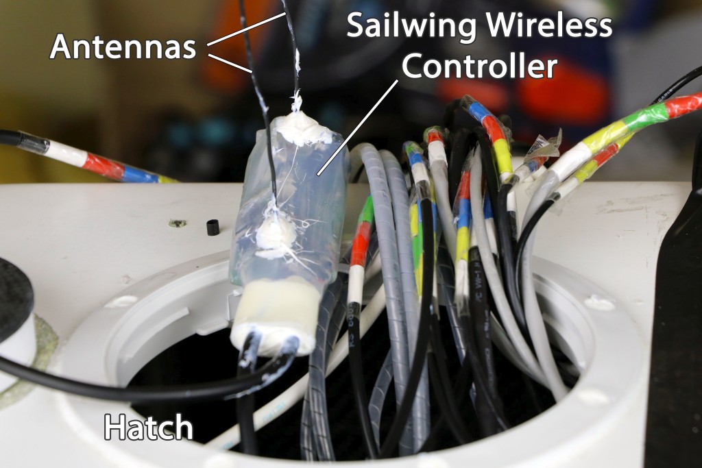
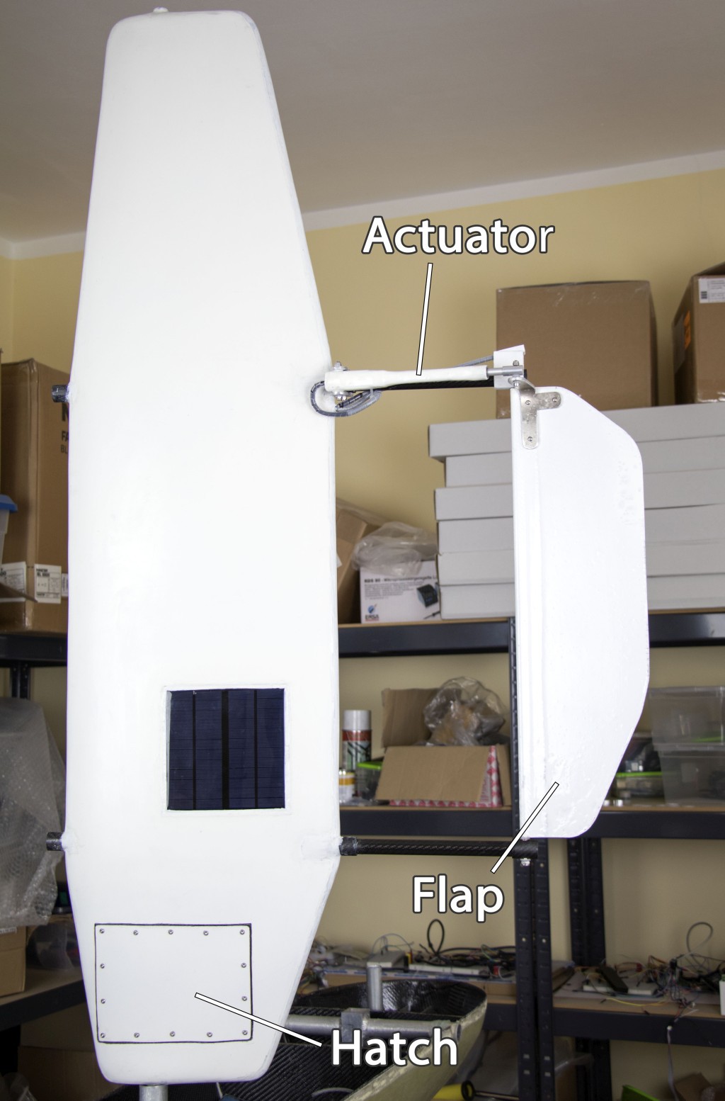
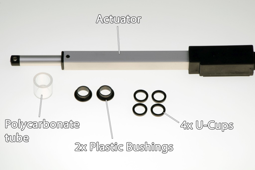
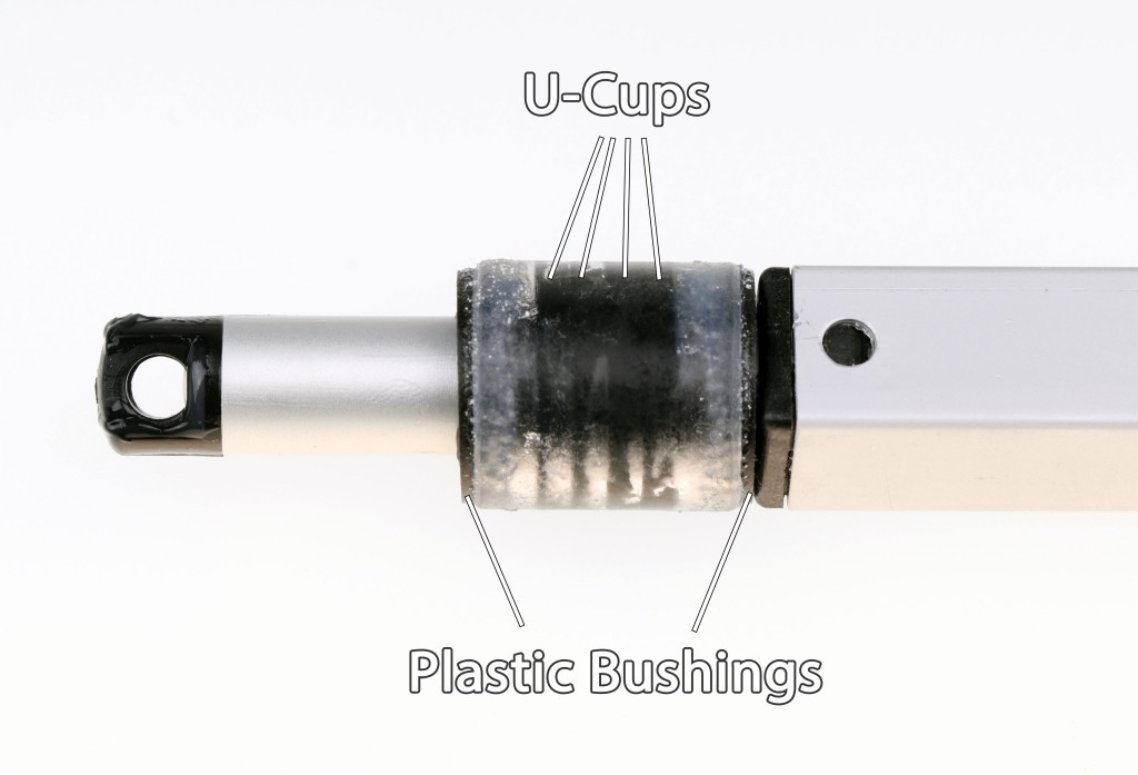
It's propelled only by the wind. The free-rotating sailwing is being adjusted by a flap just like an airplane wing.

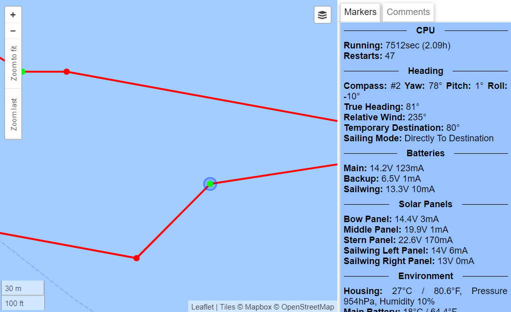
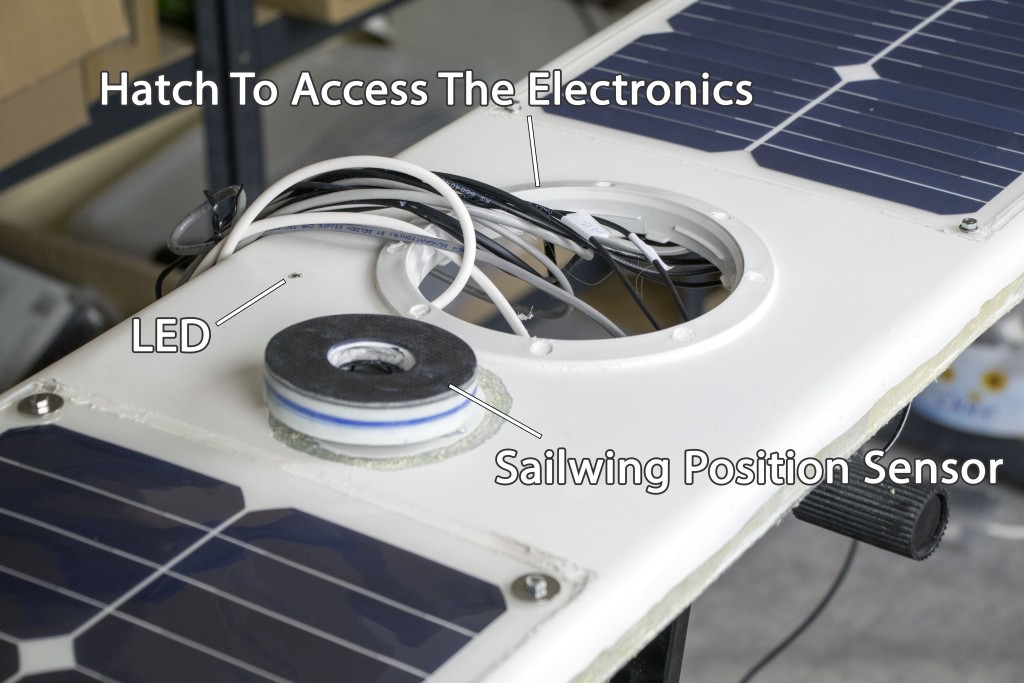
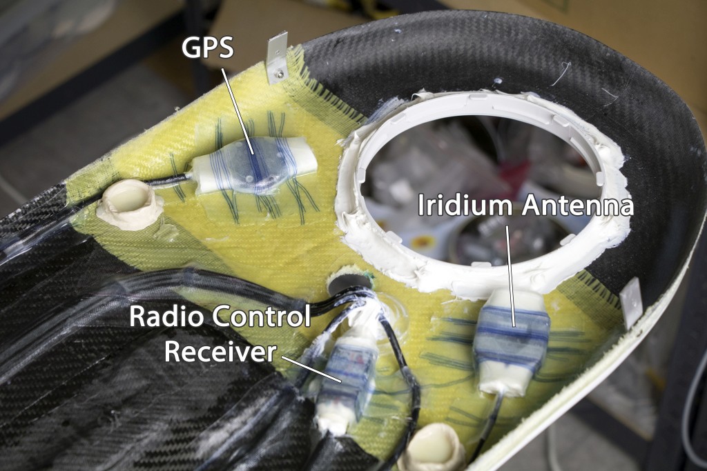
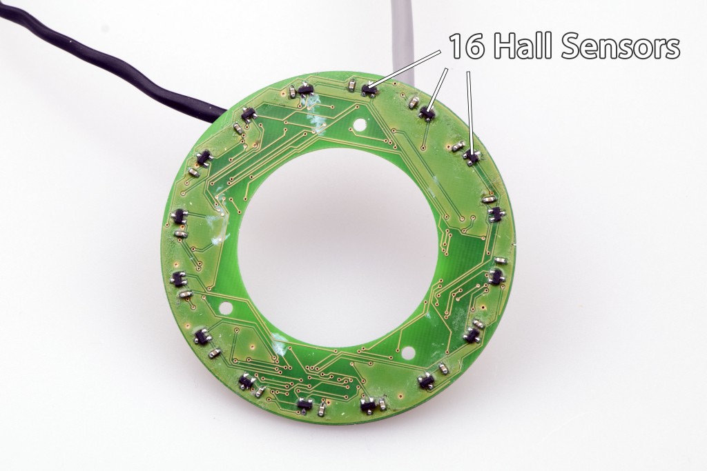
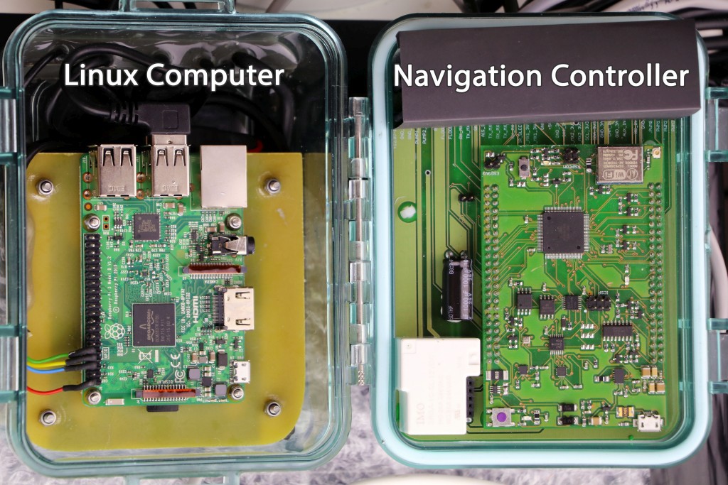
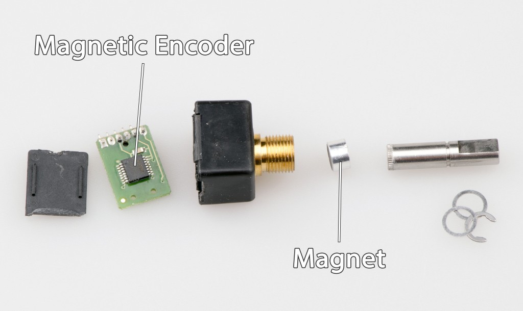
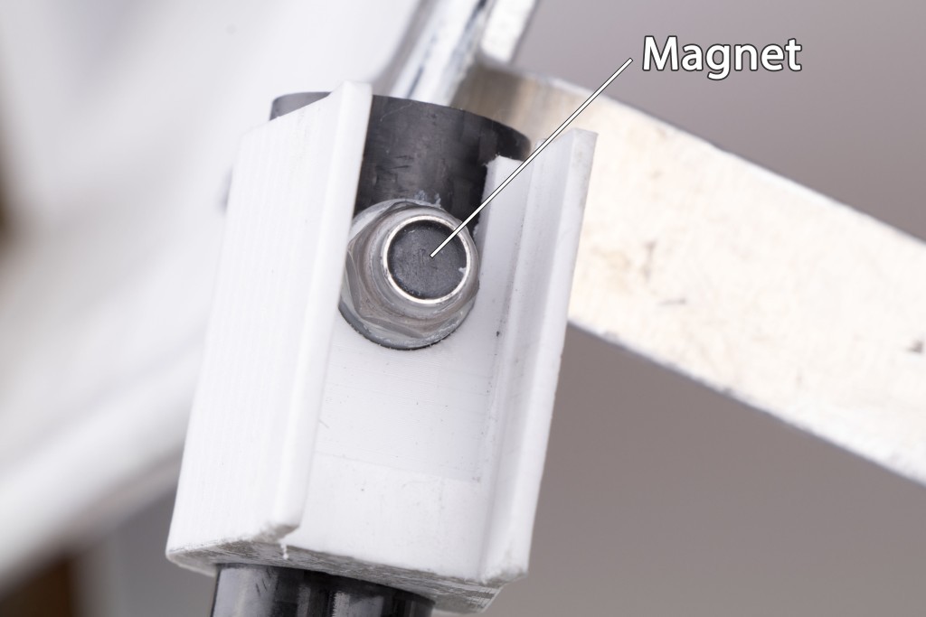
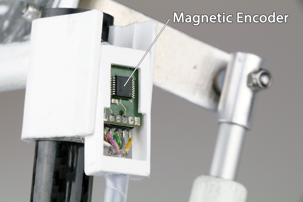
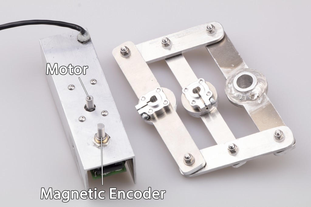
The low-power computer crunches the data from the compass, GPS, sailwing position sensor and wind sensor. It actively steers the rudder and controls the sailwing to follow the optimal path.

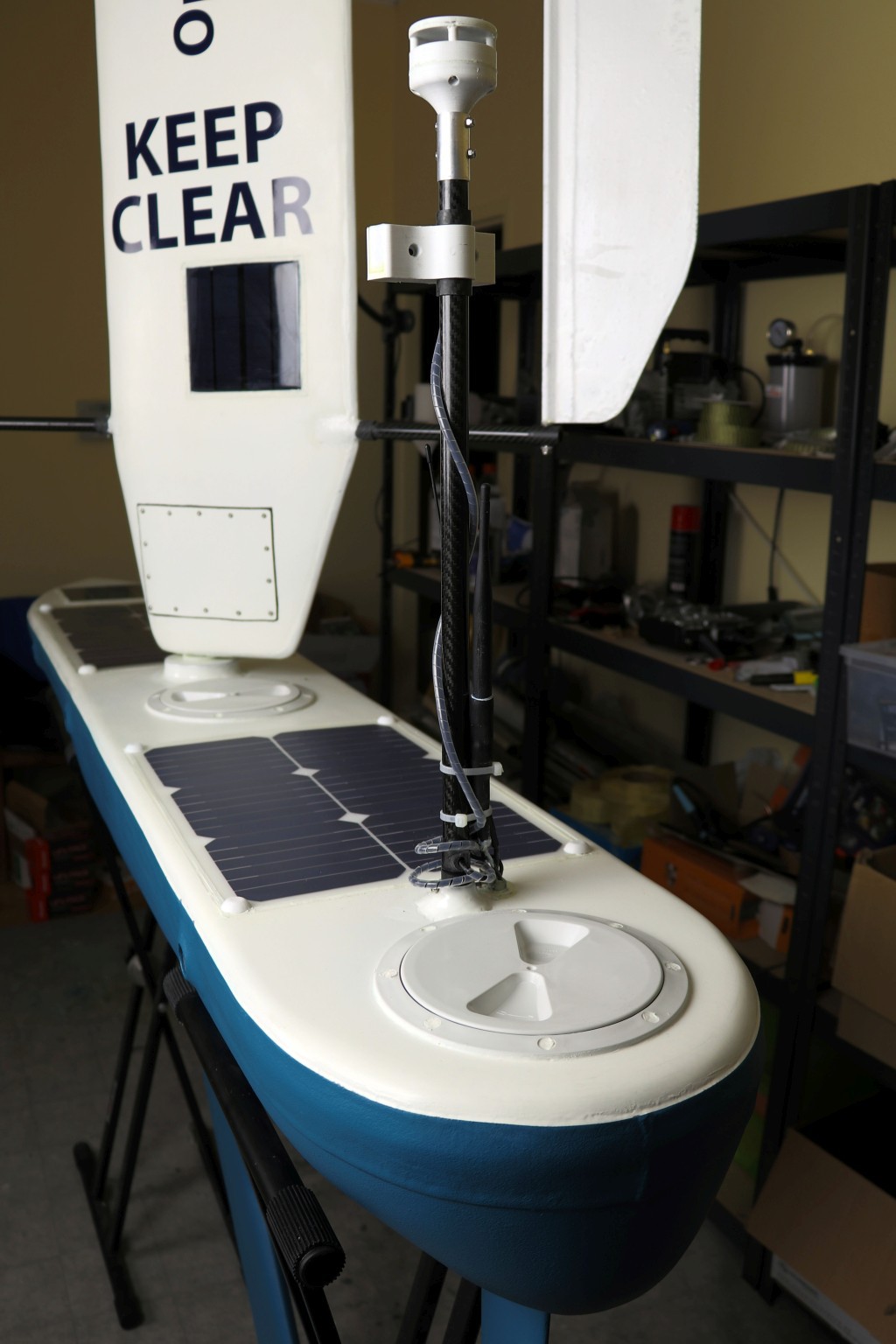
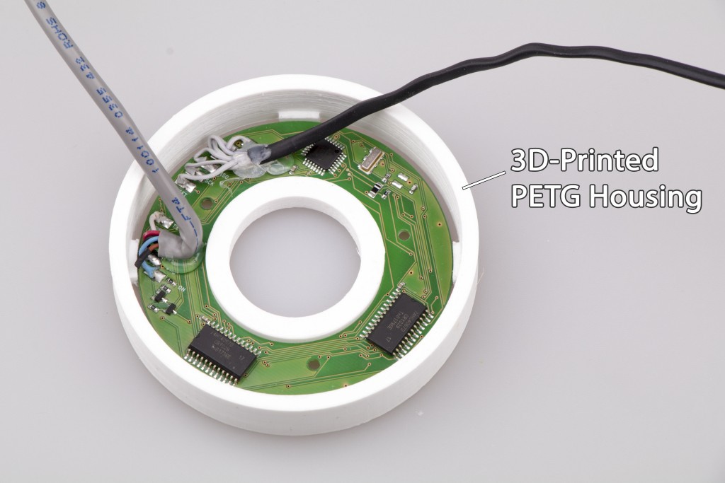
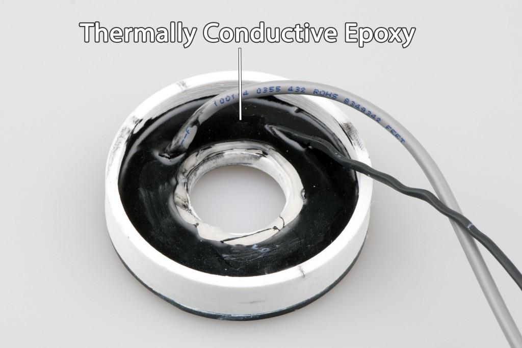
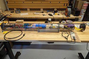
The main controller is based on Atmega2560 and is securely sealed in a waterproof polycarbonate housing. There's also a Raspberry PI computer for taking pictures and recording a video from USB webcam.
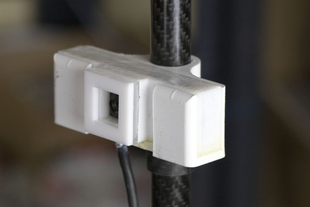
It's possible to connect a satellite modem and occasionally transmit low-resolution pictures.
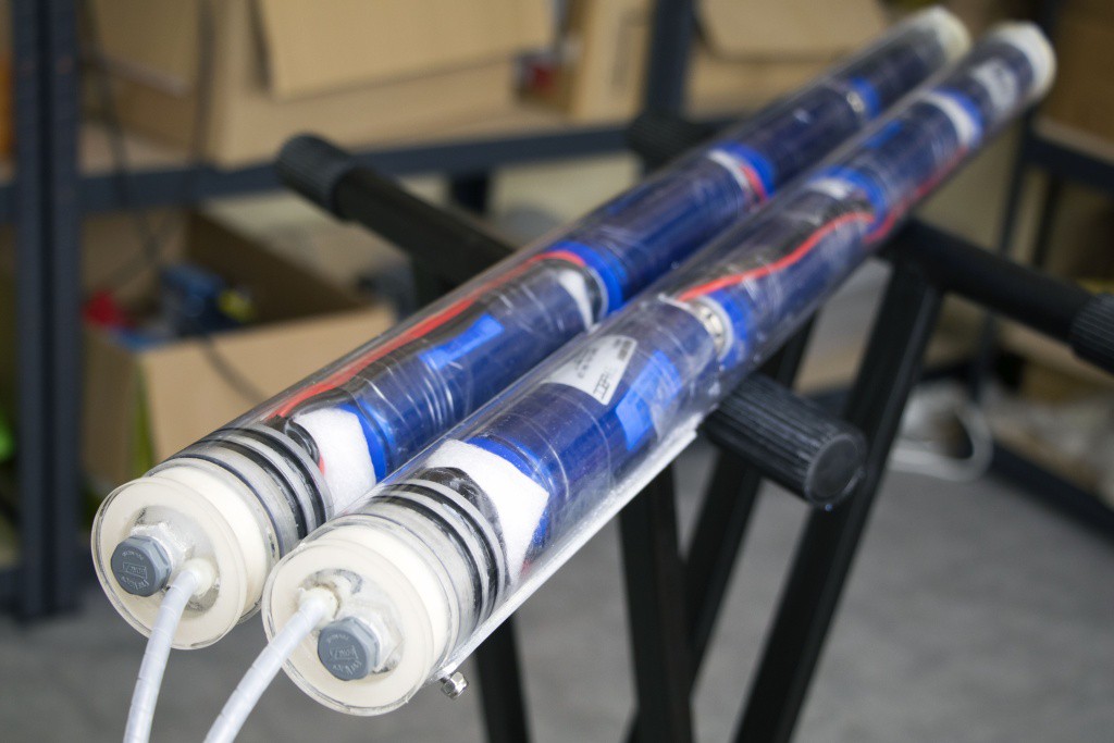
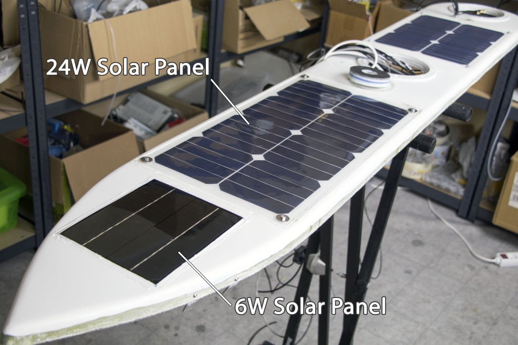
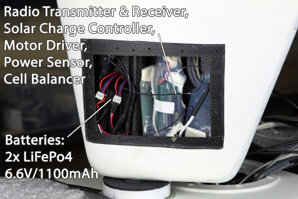
The boat runs on eight LiFePo4 30Ah cells that are recharged by the solar panels (48W in total).


 Seth Fleming-Alho
 Canine Defense Technologi
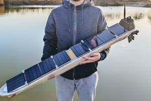
 Jianjia Ma
Any updates on attempt 3?