 oneohm
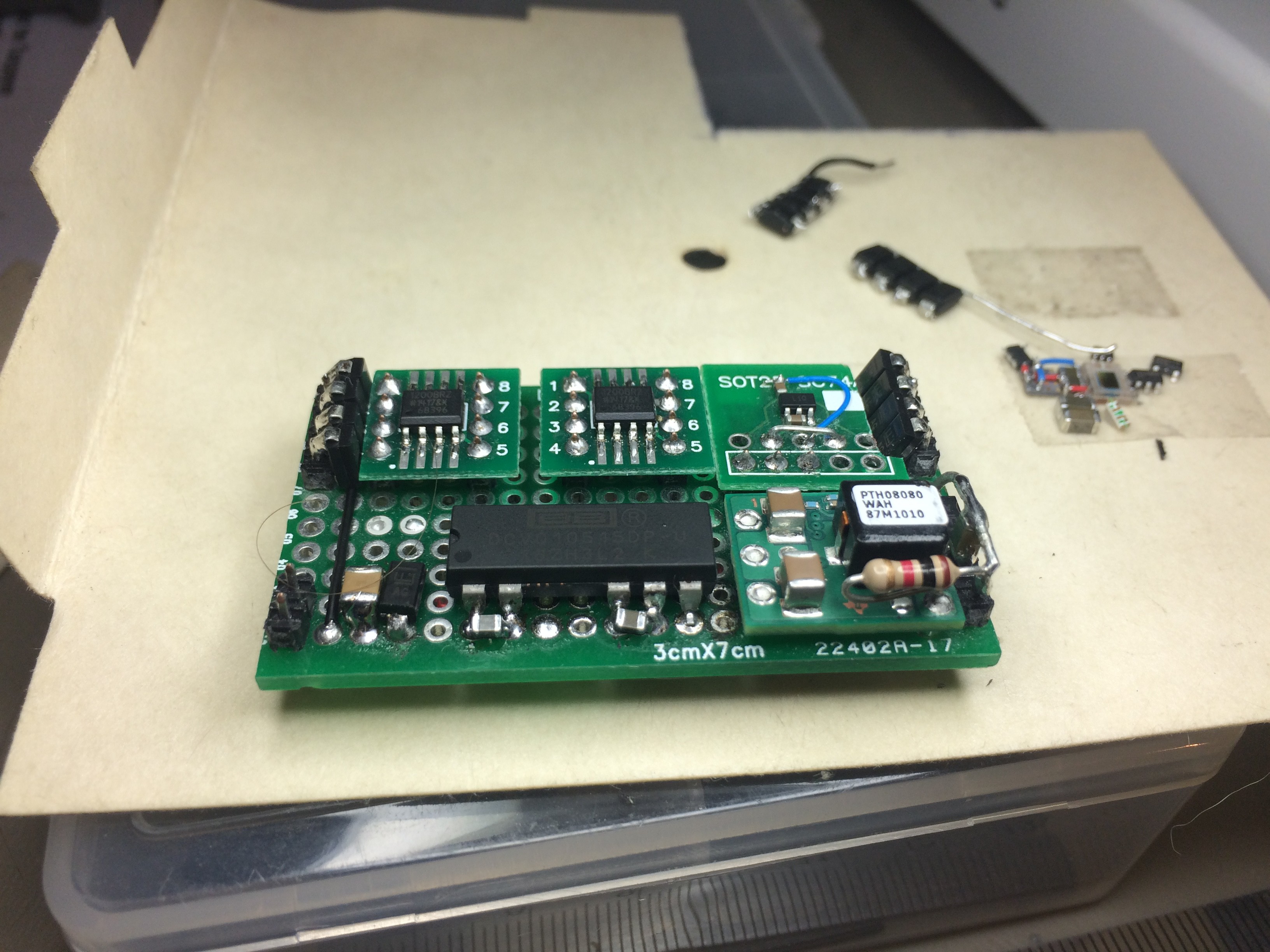
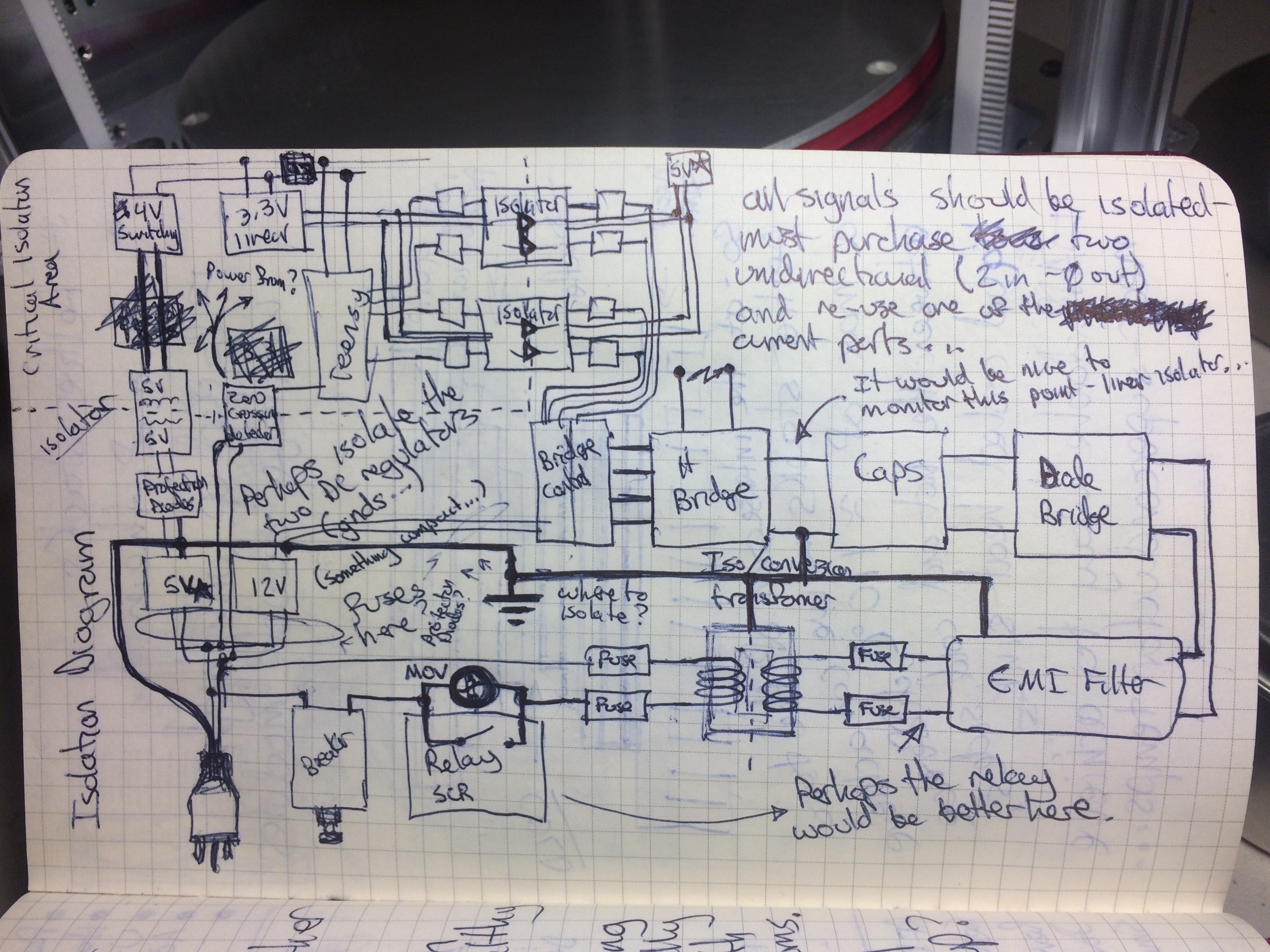
This was a build first design later kind of project.
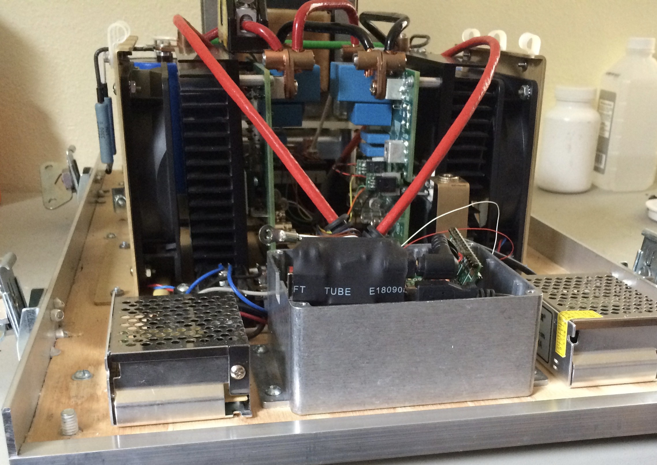
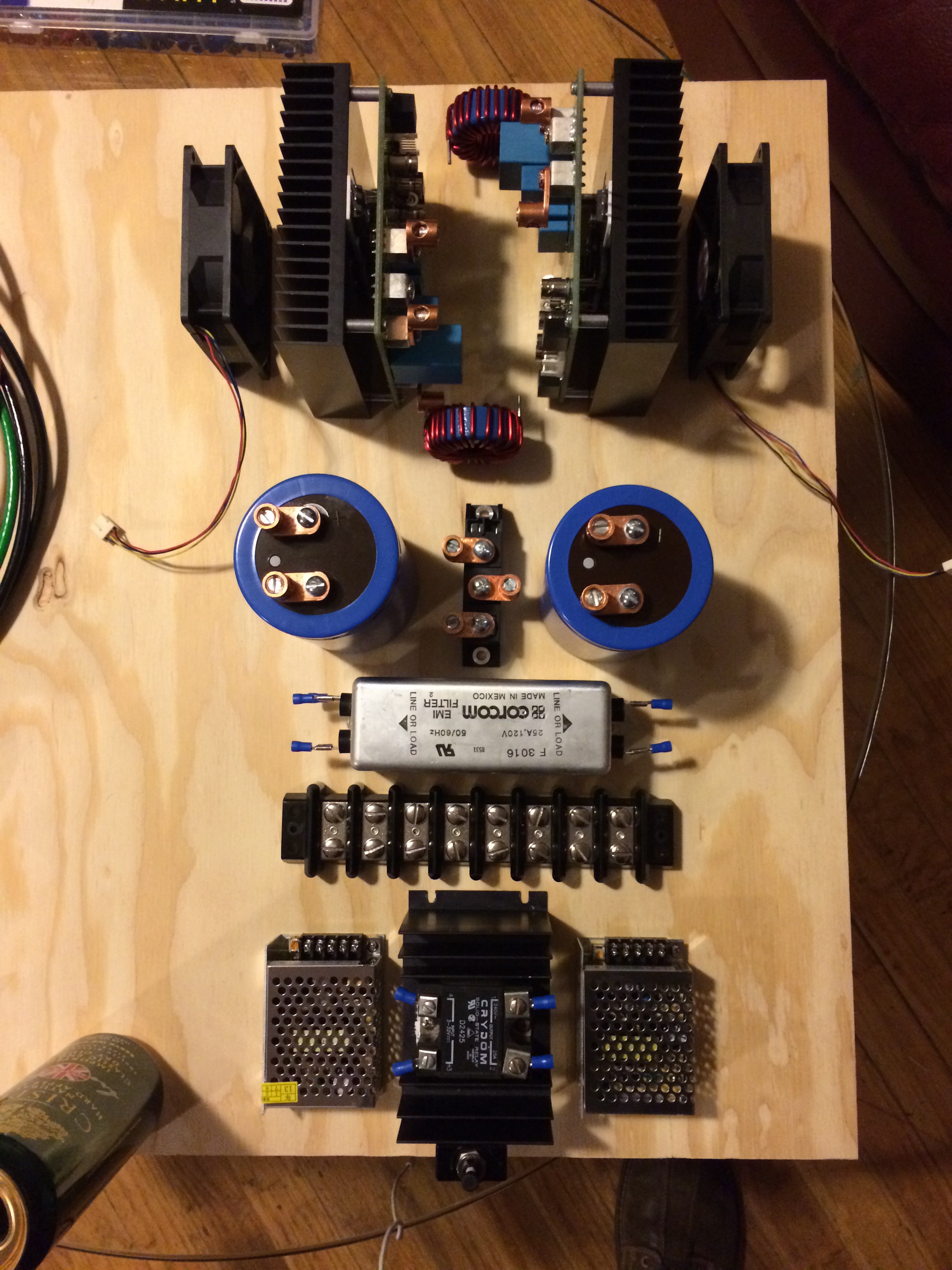
At this point I believe it is physically complete and should be functional.
I might have taken this project as far as I can alone - the real time control firmware for reliable high power regulation is a bit over my head. Anyone out there interested?
All design details will be made available - My goal is 100% open source and open hardware.
The Teensy core library uses an "MIT-like" license. Most of the code is Arduino for which the libraries are under the LGPL.


 Chris Hamilton
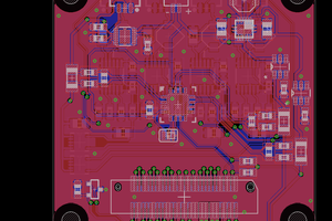
 Pinski1
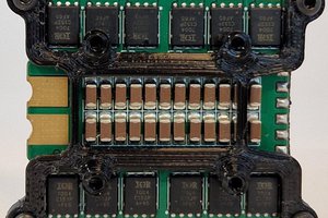
 IOkFly-BLENDERIS
 Tony
Tony
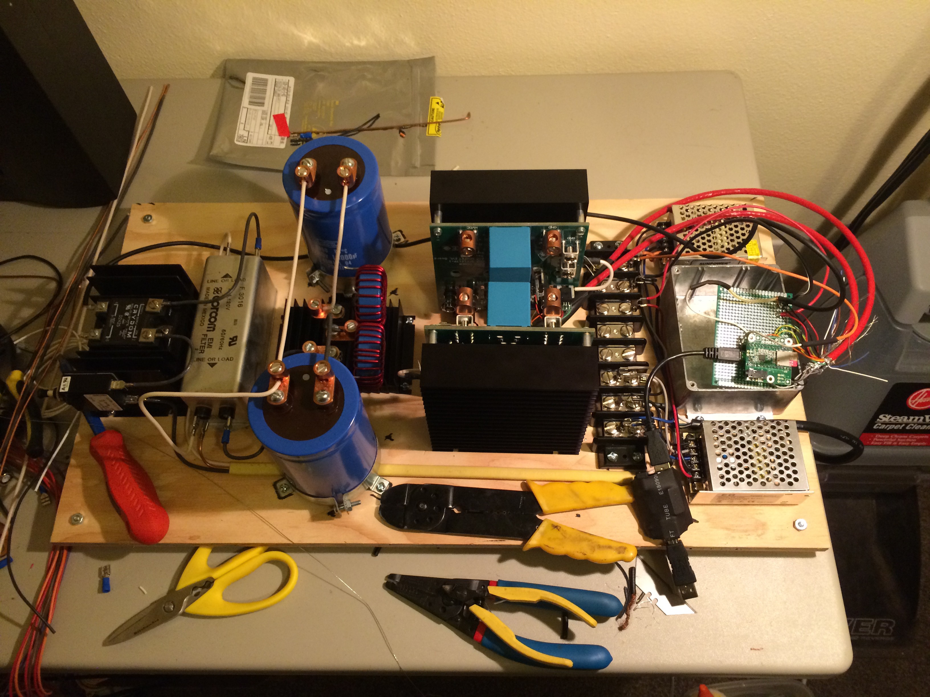
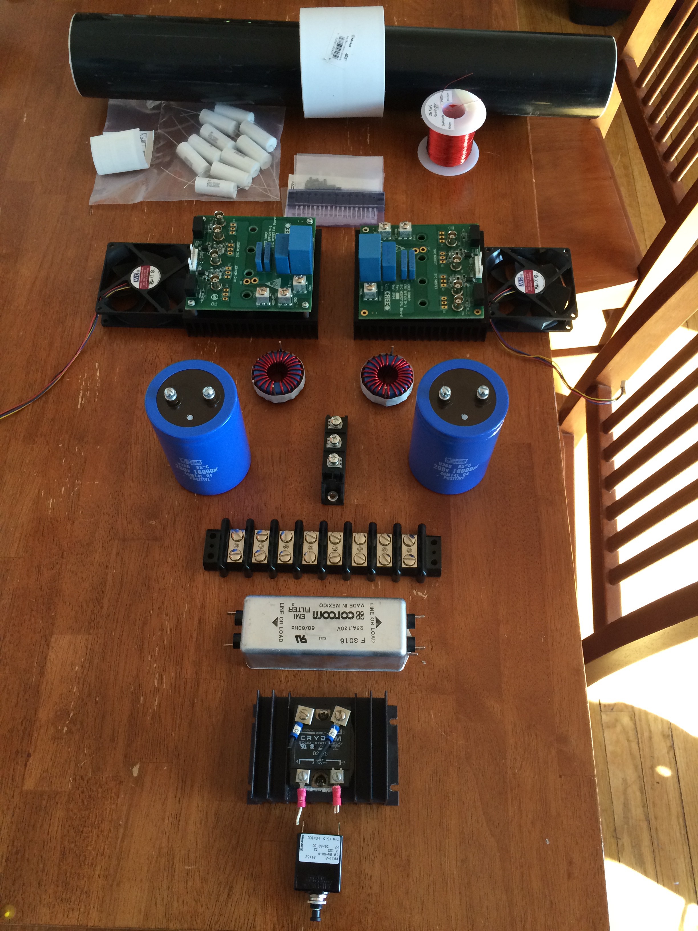
Could you describe a little bit what is this thing supposed to do, in the first place? All I see right now is a mains rectifier with big capacitors, and an H-bridge. This isn't really adaptable for "everything" - it's just a fancy name for your Tesla coil driver. Am I missing something?
As far as I can see, you claim that this can be "potentially anything" where all it got to its name is what would go into a switching power supply *before* the transformer. In that respect, it's a bit closer to a VFD or a BLDC servo drive power stage, rather than a "universal" power supply.
Running it at 10-20kW without PFC will make just about any poor infrastructure supplying the AC power rather miserable (or outright fail). Overloaded/sketchy "community wind turbine" needs to be loaded with something approaching a resistor. The sketchier the supply, the more care it needs, basically.