0%
0%
Step-and-Scan Digital Microlithography
submicron-scale patterning of silicon and dielectrics
 helge
helgeBecome a Hackaday.io member
Already have an account? Log in.
Just one more thing
To make the experience fit your profile, pick a username and tell us what interests you.
Pick an awesome username
hackaday.io/
Your profile's URL: hackaday.io/username. Max 25 alphanumeric characters.
Pick a few interests
Projects that share your interests
People that share your interests
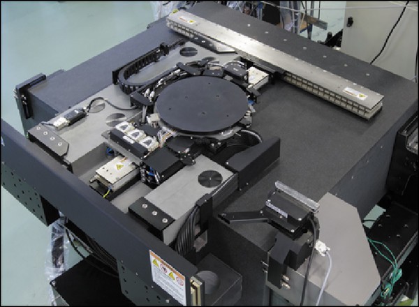
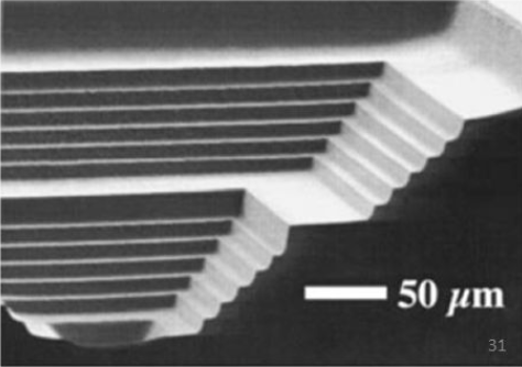
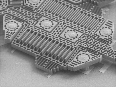
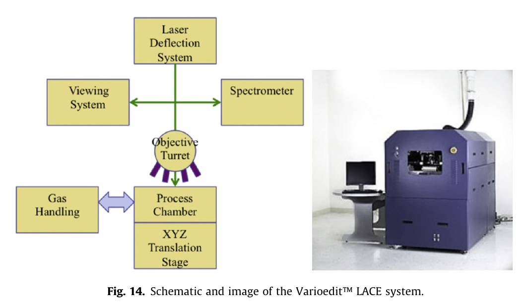 there are a few more juicy pictures of macroscopic terraces etched into thick wafers, so this really is a thing. Unfortunately there only seem to be one or two pictures showing the machine so it's doubtful anyone out there really owns and operates it (or they're not allowed to talk about it, exception:


 Paul McClay
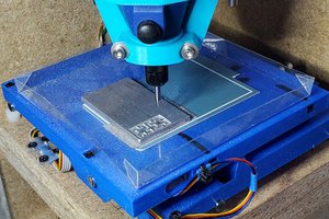

 Supplyframe DesignLab
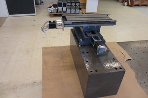
This reminds me of my mis-spent youth! I used to work on Ultratech projection steppers in the early days of 150mm wafers. They used mercury arc lamps as a UV source. They also had a pneumatic auto-focus system that mostly worked.