 Dave Ehnebuske
Why another clock?
The clocks people use to tell the time of day consist of a display to show what time it is, a timebase to drive the display, and a case to hold them. The number of ways people have found to build clocks -- to vary the display, the timebase and the case -- is truly astonishing. Sadly, since the development of the super-cheap, accurate quartz clock movement almost all of the interesting new clocks use that as their timebase and only vary the case and the display.
There are exceptions, of course. Some interesting new clocks use traditional mechanical movements such as pendulums or balance wheels. Others use the 50 or 60 Hz of the AC power as their timebase. A few use standard time signals such as those from WWV, time.nist.gov or the GPS constellation to keep their primary timebase synchronized closely with Coordinated Universal Time. But for the most part, hobbyist clock builds and commercial clocks for consumer use all employ a quartz movement and differ from one another just in their the case and display.
For commercially made clocks the reason is obvious, but why do our clock builds go down this same path so often? Personally, I find the timebase part of a time-of-day clock just as fascinating as the case and the display. Maybe more so. I guess that’s what motivated my bendulum clock build.
The fun and success I had with that build led me to think about other ways I might make a timebase for a clock. In the course of that build I struggled for quite a while with the fact that its bendulum, like all physically oscillating timebases, from pendulums to quartz crystals, changes its rate slightly as the temperature changes. Whenever something physical oscillates back and forth, thermal expansion tends to change the rate at which it does so. To counteract this, you can either compensate for it by observing how it changes and counteracting it in the design (the approach I took with the bendulum) or try to hold the temperature constant (as is done with an “oven controlled crystal oscillator” or OCXO). But is there another approach all together?
How is this one different?
After having the question roll around in my head for quite a while, one day a possible answer just sort of arrived out of nowhere: radioactive decay.
The average number of decay events that occur in a sample of a long-lived radioisotope changes very slowly over time and in a way that is completely predictable. Importantly, the rate of decay doesn’t change at all with changes in temperature, pressure or other environmental conditions. What I started to think about was whether I could derive, say, a 1Hz timebase from the radioactive decay of a small, safe sample of some long-lived radioactive substance.
The problem is that although the rate of decay is completely predictable over the long haul, every decay event is completely random in time. A sample small enough to be both obtainable and safe will necessarily have a number of decay events per second that’s pretty small. That means the number of decay events that occur in any given second will be unpredictable.
Suppose you had a sample you knew underwent 10 decay events per second, on average. If you drove a clock by counting decay events, moving the second hand ahead by one each time you got to a multiple of ten, the clock would keep time. On average. But in the short term it would always be wrong. Sometimes the clock’s “seconds” would occur quickly and sometimes there would be long pauses between them. If you’ve ever heard a Geiger counter you know how irregularly the clicks come. I don’t see any way to directly derive a regular timebase out of that.
But the fact that the average decay occurs so predictably means that we should be able to use such a radioactive sample to adjust the run rate of a not-so-good 1Hz timebase so that it stays very close to correct and over the long haul is spot on. That would be a pretty good clock.
So what are the downsides? Why wouldn’t this work perfectly? The chief downside I see is that any practical radiation detector will count not just decay events from the radioactive sample, but also events from the “background” -- from incoming “cosmic rays,” from the decay of naturally occurring radioactive atoms in the earth and from any radioisotopes added to the environment from our various nuclear activities. Fortunately, in most places on Earth’s surface the background radiation is pretty low and relatively constant. Except, in some places, for radon.
According to the research I’ve done, it appears that by far the biggest source of variation in the background comes from weather-driven and seasonal changes in the level of radon in enclosed spaces like houses. In some places these changes can be be quite large and quick -- e.g. vary by a factor of ten in a matter of an hour or so. The weather-driven changes are caused by changes in atmospheric pressure, by wind and by precipitation. Seasonal changes -- higher in winter than summer -- are driven mostly by changes indoor-outdoor temperature differential and by differences in ventilation. Whether this is a big problem for this project, I’m not at all sure at this point, but if it becomes obvious it’s significant, I should be able to use a background detector -- the same kind of detector I choose for the radioactive source, but away from the source -- to null out the effect. For now I plan to proceed as if there’s no problem.
First steps
So, what should I use for a radioactive source and for a detector?
Let’s start with the source. The project needs a source that’s takes a long time to decay so that the decay rate doesn’t change much over time. I need to be able to obtain the source easily without running afoul of regulations or laws. And the source needs to be safe to have around the home. The most obvious choice is an Americium-241 source from a smoke detector. 241Am has a half-life of 432.2 years and sources are easily and legally obtained from smoke detectors found in just about every building. Like the one I replaced a few months ago.
So, what about a radiation detector? 241Am mostly decays by emitting alpha particles, but its decay also produces some gamma radiation. Individual alpha particles are hard to detect because they don’t get far before they get absorbed. They can be detected by by PIN diode detectors, but making one requires more skill with designing and building op amp circuits than I have. I tried and failed repeatedly. The signals involved are very small and mains interference gets into everything. Alpha particles can also be detected using various other kinds of specialized detectors, none inexpensive. On the other hand, low-level gamma radiation is easily and reliably detected using a commercially available low-end Geiger counter.
I made an adjustable stand that let me put a Geiger counter near a 241Am smoke detector source.
Here, the red PCB is the Geiger counter. The Geiger tube is on the back of the board and runs across its width along the lower edge. The 241Am source is mounted on the small platform under the Geiger counter. It’s the gray cylinder that looks like the top of a cap-head screw. The platform can be adjusted by turning a screw behind the Geiger counter, moving the source closer to or further away from the Geiger tube.
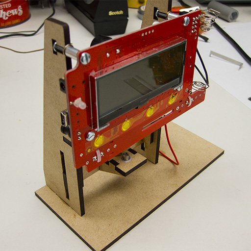
With no source installed, the Geiger counter clicked about ten times a minute on average. With the source installed I was easily able to adjust the distance between the it and the Geiger tube to get about 120 times a minute -- two clicks per second.
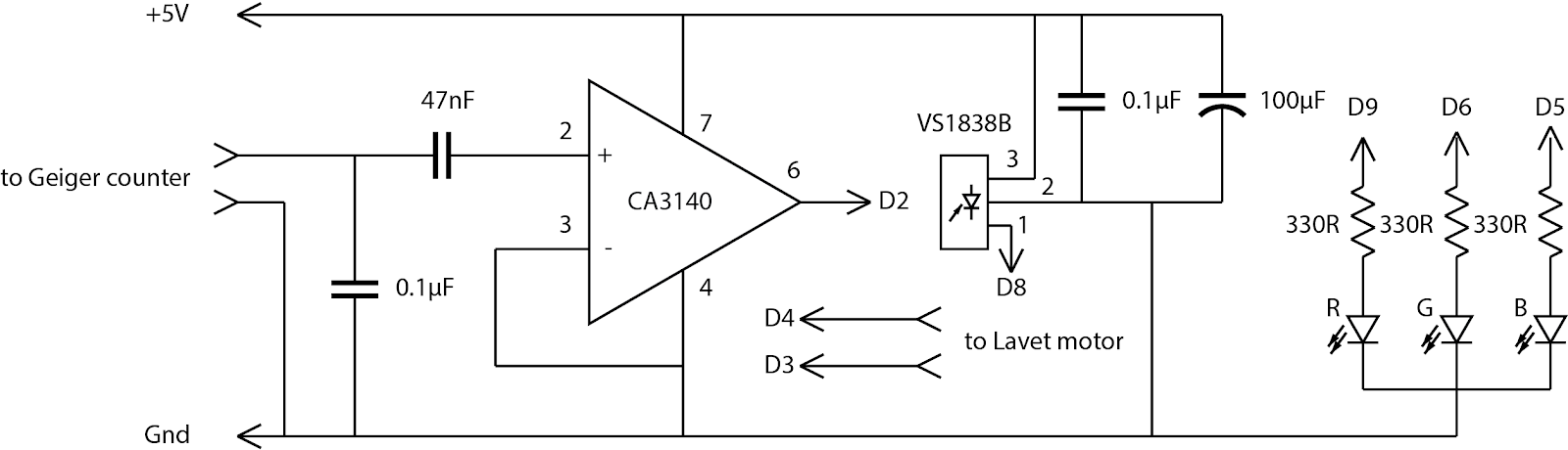
To create a suitable input for an Arduino Uno external interrupt, I used an op amp breadboarded in a simple circuit to level-shift and shape the audio click signal the Geiger counter produces each time a beta particle or a gamma photon goes through the tube. I hooked the output to an Arduino Uno digital pin 2 and with the help of a simple sketch, the Arduino was counting 241Am atoms falling apart one by one.

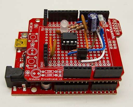
I breadboarded this interface together with a DS3231-based RTC as you can see, below.

I connected this up and captured the number of Geiger counter clicks that occur between one-second ticks of the RTC. I used the count to update an exponential decay moving average with a decay period of an hour. After running for a few minutes, the click-count average smoothed out at about 2.233 clicks per second. Because of the randomness of the Geiger counter clicks and the relatively short exponential used in the moving average, the average bumped up and down by a few percent with each tick of the RTC, but showed no long term trend. The lack of long-term trend is encouraging. The few percent bumps up and down in an hour-long average means I can only rely on really long term averages if I want to keep the clock display within a few seconds of the correct time.
The basic idea for the algorithm I plan to use treats decay events as “fuel” to drive the clock display. We count them up as they occur, and decrement the count by the average decay rate each time we drive the display forward by one second. To make things nice and regular we gate driving the display with a not-too-accurate timebase, in this case the micros() clock in an Arduino Uno. If, over time, the gating causes the click count to rise, the clock is running too slowly and we speed up the gating timebase a little. If the count drops, we slow the gating timebase down to slow the clock. Over the course of a day the clock will be just about right on time because the number of decay events per day is quite stable. Chances are quite good that at the end of a day, the number of decay events my 2-counts-per-second 241Am sample will have undergone will be very close to 2 * 60 * 60 * 24 = 172,800. And, importantly, whatever error exists will be random, not systematic. It will even out, not accumulate, as the days go by.
I designed a simple Arduino shield containing my Geiger counter interface, an RGB LED, an IR remote receiver and a connector for a Lavet motor clock display, breadboarded it to check the design out and then assembled it on an Arduino shield proto-board. I’ll use the LED to indicate the clock’s status, and the IR receiver to receive commands from a remote control to adjust the running clock.
As you can see, there's not much to it. Here's the proto-board shield.
Next steps
I've written the first several passes at the Arduino code for the clock and am trying out various approaches to making the clock display move forward uniformly. I've tried a bunch of PID-loop variants but haven't yet found one that works as well to even out the clock's operation while still allowing for relatively quick adjustment of the run speed.