 Capt. Flatus O'Flaherty ☠
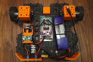
So why four channels? ........ The device is specifically designed for agri - robots where there are normally 4 drive wheels - four wheel drive. If one of the wheels is providing more torque than the others, unless it 'slips', it will effectively be fighting against the others and wasting energy and reducing overall traction. The most advanced motors are servo motors with optical encoders and these give all the sophisticated control features that we could ever want! ...... But on the cheaper motors drives there may not be analogue signal output for torque or current so in this case we'd have to build our own. It's really not a problem as the board is dead easy to build and works really well. Slightly more difficult to code as reading AC signals requires sampling of the whole AC wave and, normally, integrating it. Here, I've just calculated the peak amps during the cycle and used them to give the relative torque of each motor ..... Simples!
* The current sensor is not breadboard friendly so it's better to go straight for PCB mounting for testing these devices.
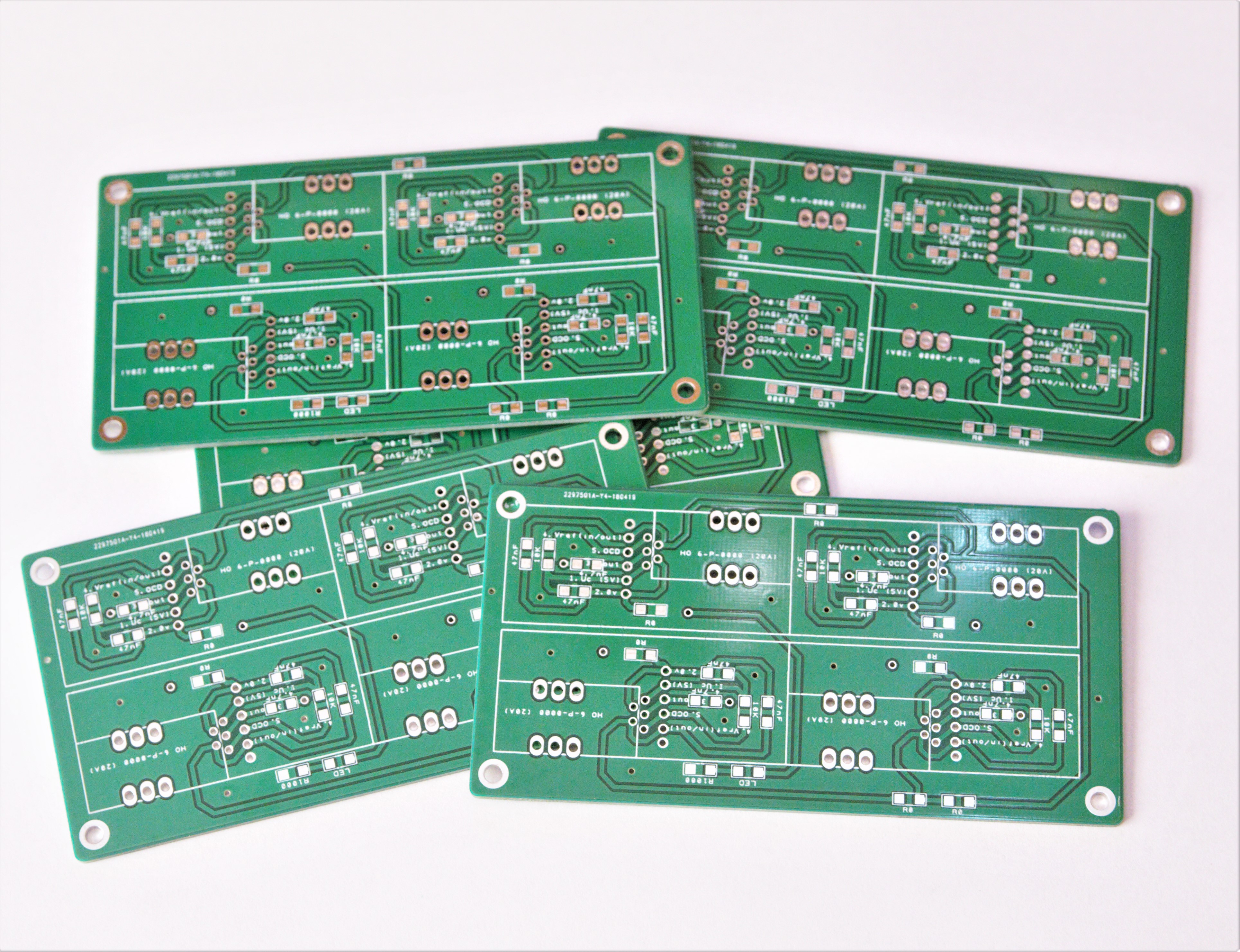
* All the SMD components are 1206 and are easy to hand solder so no stencil is required.
* Datasheet is here: https://docs-emea.rs-online.com/webdocs/15c5/0900766b815c552a.pdf
* The sensors are 5v friendly so perfect for Arduino Uno, Mega etc.
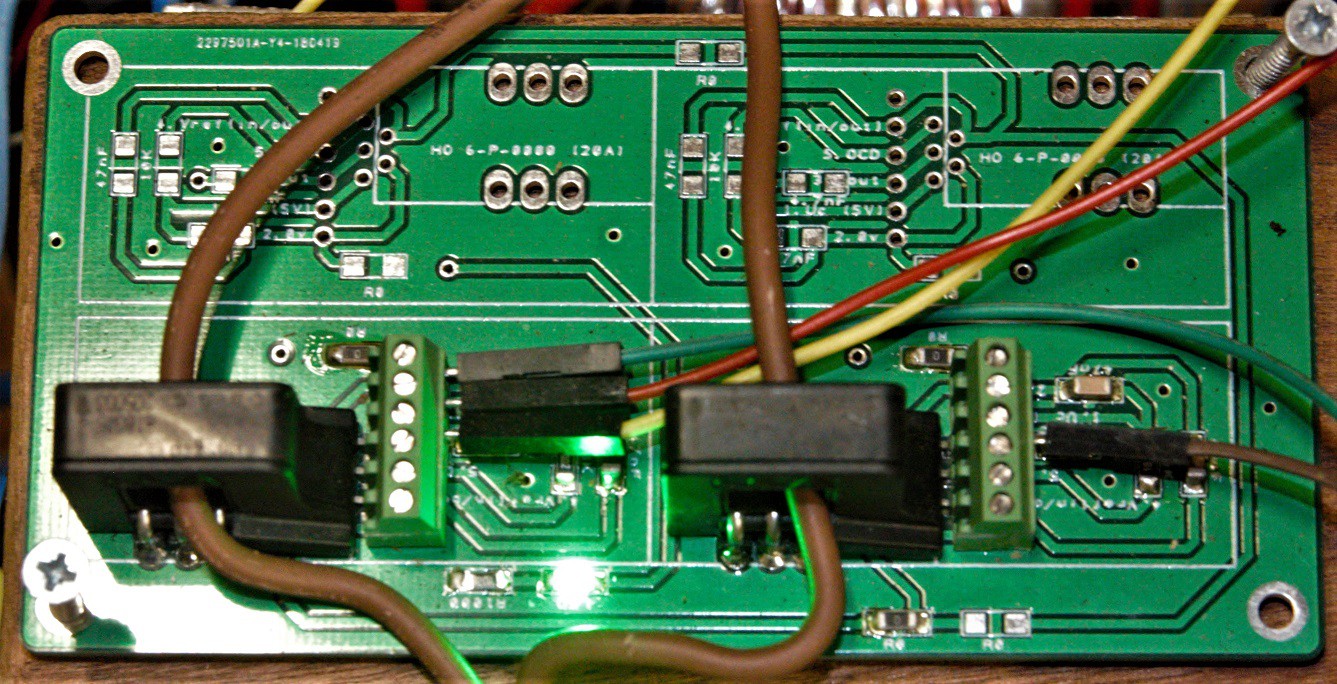
 Quickly solder on the components and ready to test.
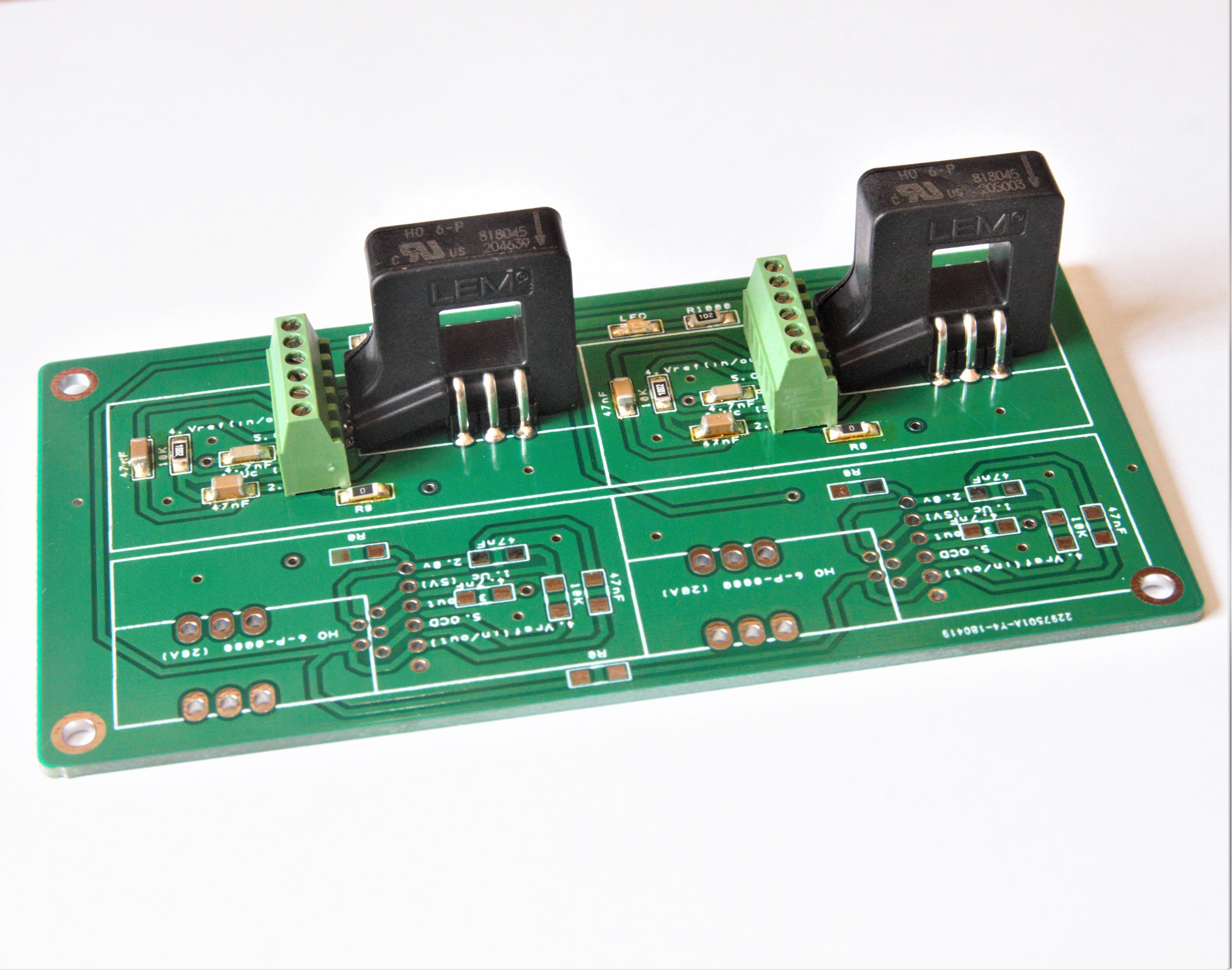
 matop
matop
 Christopher Xu
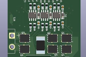
 Navid sabet
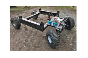
This would be perfect, but I am limited with space, especially with height so is there a smaller sensor? I found the NP series, but was a bit confused about how it works, since it doesn’t have a hole for the wire. Do you hook up the current to a pin on the sensor?