 Paul Gould
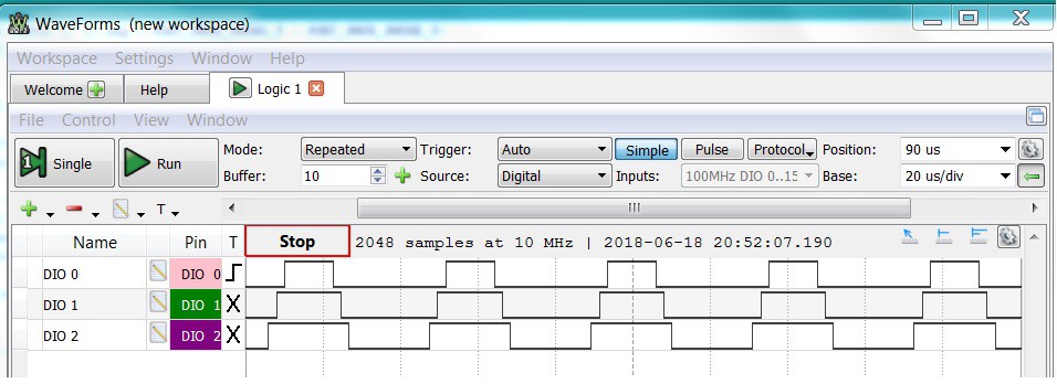
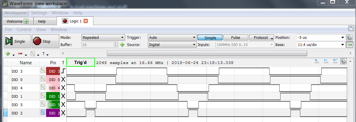
In an effort to make the controller accessible to more makers I've strated designing an Arduino based system. It uses the SAM D21 G 32-bit micro-controller as used on the MKRZERO board. This chip has an advanced Timer Counter Controller which can generate three centre aligned PWM signals. After sorting out the correct pin mapping it is up and running.
The code is based on information provided in the Arduino forum by MartinL.
https://forum.arduino.cc/index.php?topic=346731.0
Now with deadband
I will create a github shortly
Next up dual SPI. One for the absolute magnetic encoder sensors and the other for the FET gate Driver IC.
PID and FOC should be easily ported across.
Voltage and current measurement may be difficult because the Arduino doesn't support free running sequential ADCs very well.
The SAM D21 does not have CAN commucations so it will need RS485 and USB.
Discussions
Become a Hackaday.io Member
Create an account to leave a comment. Already have an account? Log In.
In this example you are right. This is just the RAW PWM signals to make sure I could get three centre aligned PWM signals @ ~24kHz out of the Arduino SAM D21. Next is to add the Field Oriented Control code to generate the 3 Saddled Sine waves.
Are you sure? yes | no
Shouldn't the three waveforms be 120 degrees apart from each other? The motor is stalling with what you show.
Are you sure? yes | no