0%
0%
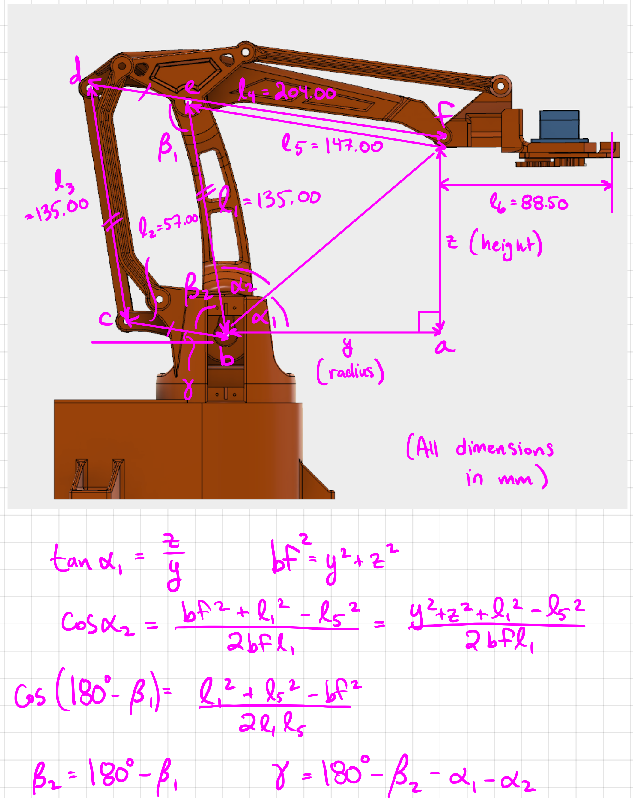
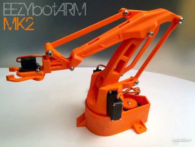
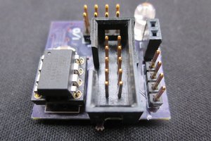
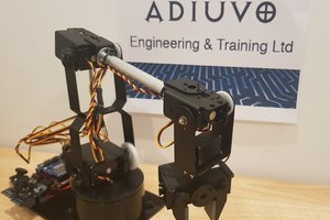
STM32 Robot Arm Controller
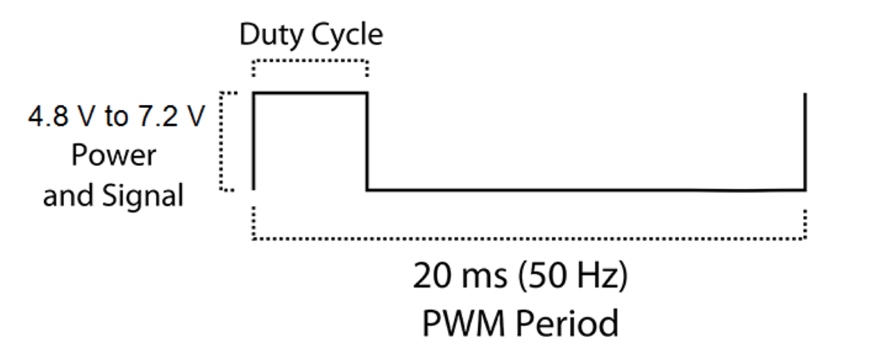
Provides power, PWM voltage level conversion, and a Wii Nunchuck connector. Designed to work with the EEZYbotARM MK2.
Become a Hackaday.io member
Already have an account? Log in.
Just one more thing
To make the experience fit your profile, pick a username and tell us what interests you.
Pick an awesome username
hackaday.io/
Your profile's URL: hackaday.io/username. Max 25 alphanumeric characters.
Pick a few interests
Projects that share your interests
People that share your interests
 Adam Taylor
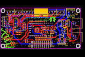
 sandy
sandy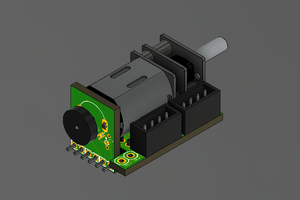
 Holotype Robotics