Rudolph
A project three years in the making, rudRemote takes an old R/C transmitter (or a new one, or a game controller, or a box of parts) and creates a new controller that speaks CRTP (Crazy RealTime Protocol, the language of the Crazyflie 2.0) to whatever is listening.
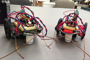
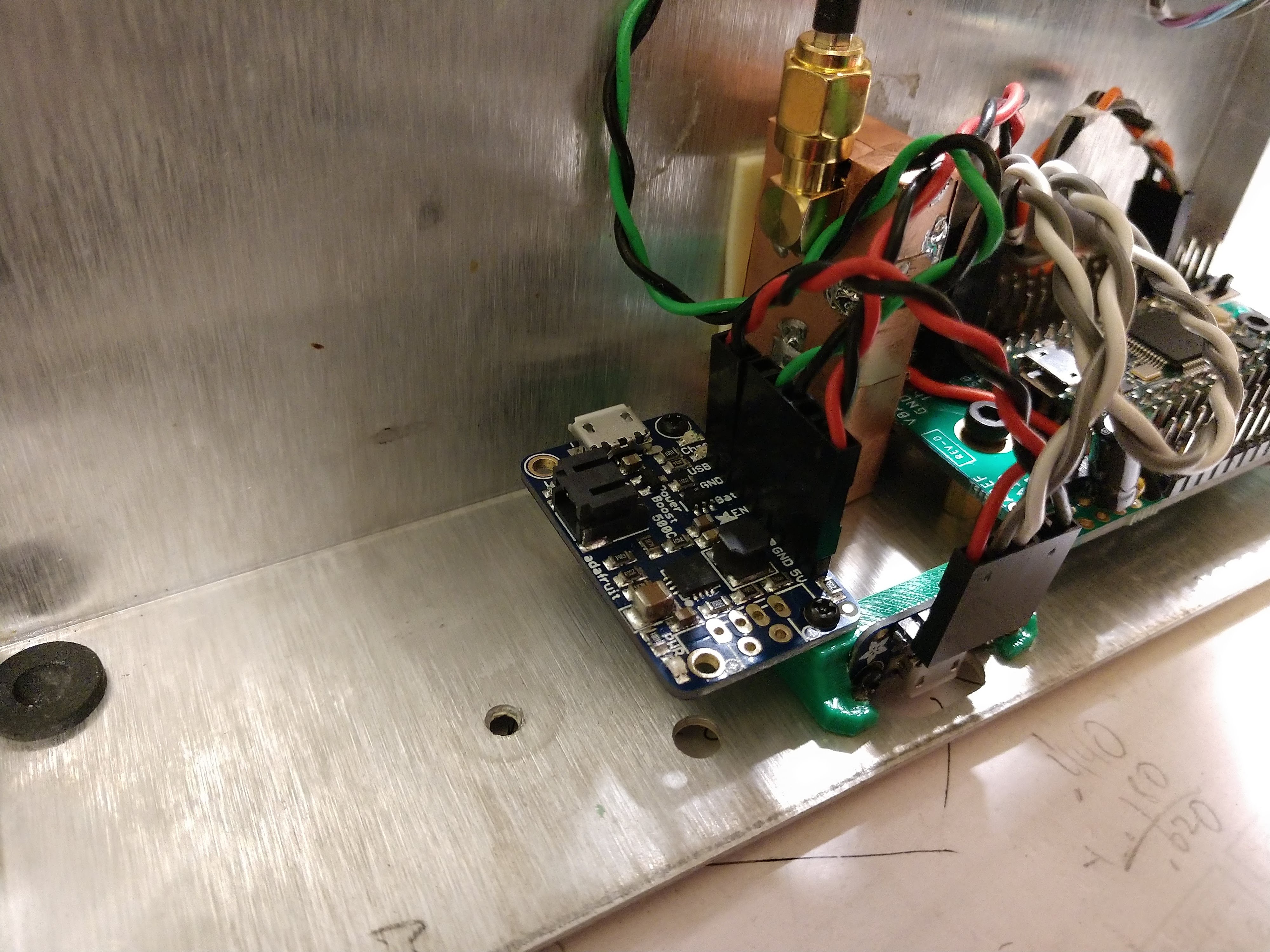
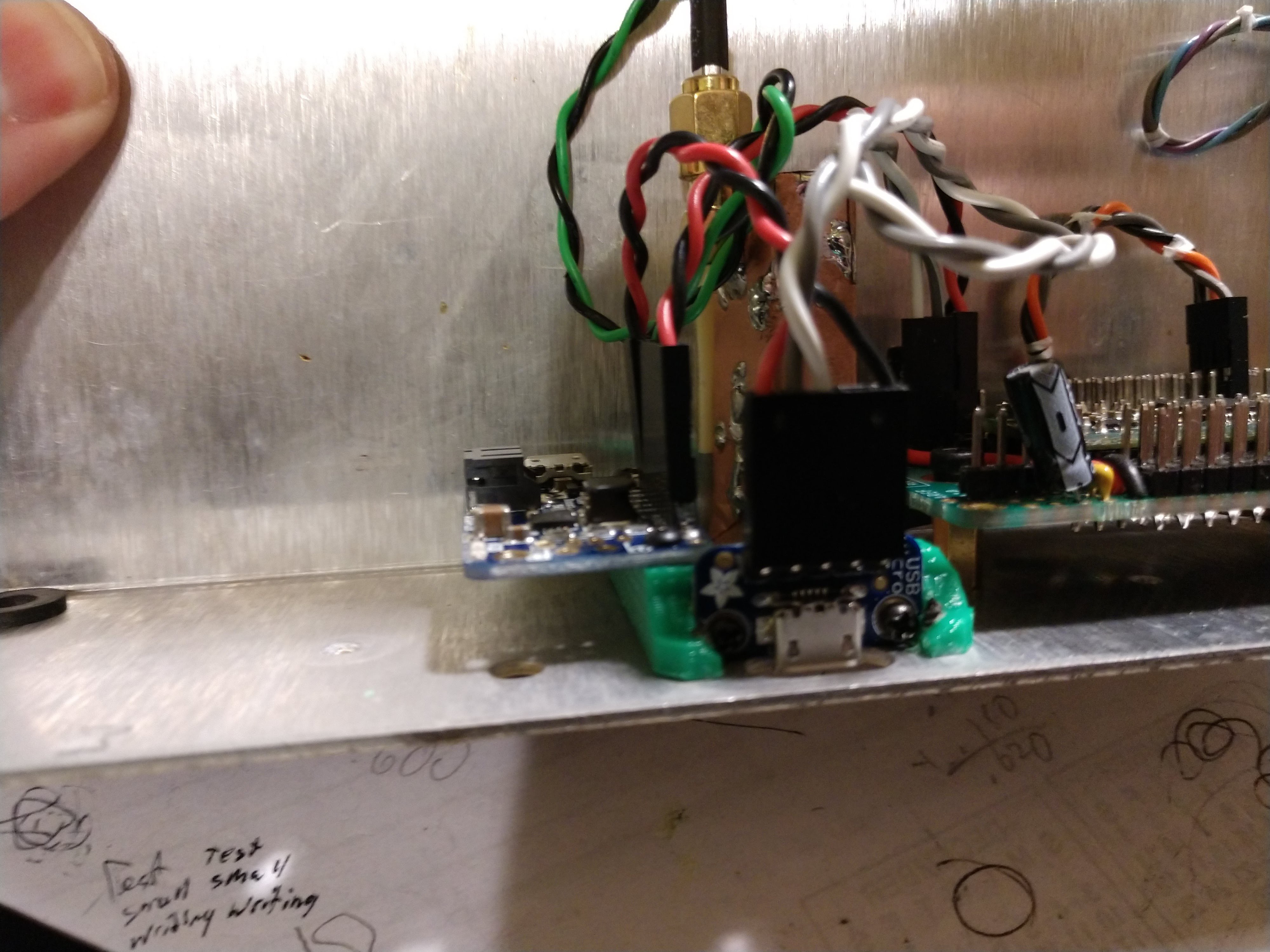
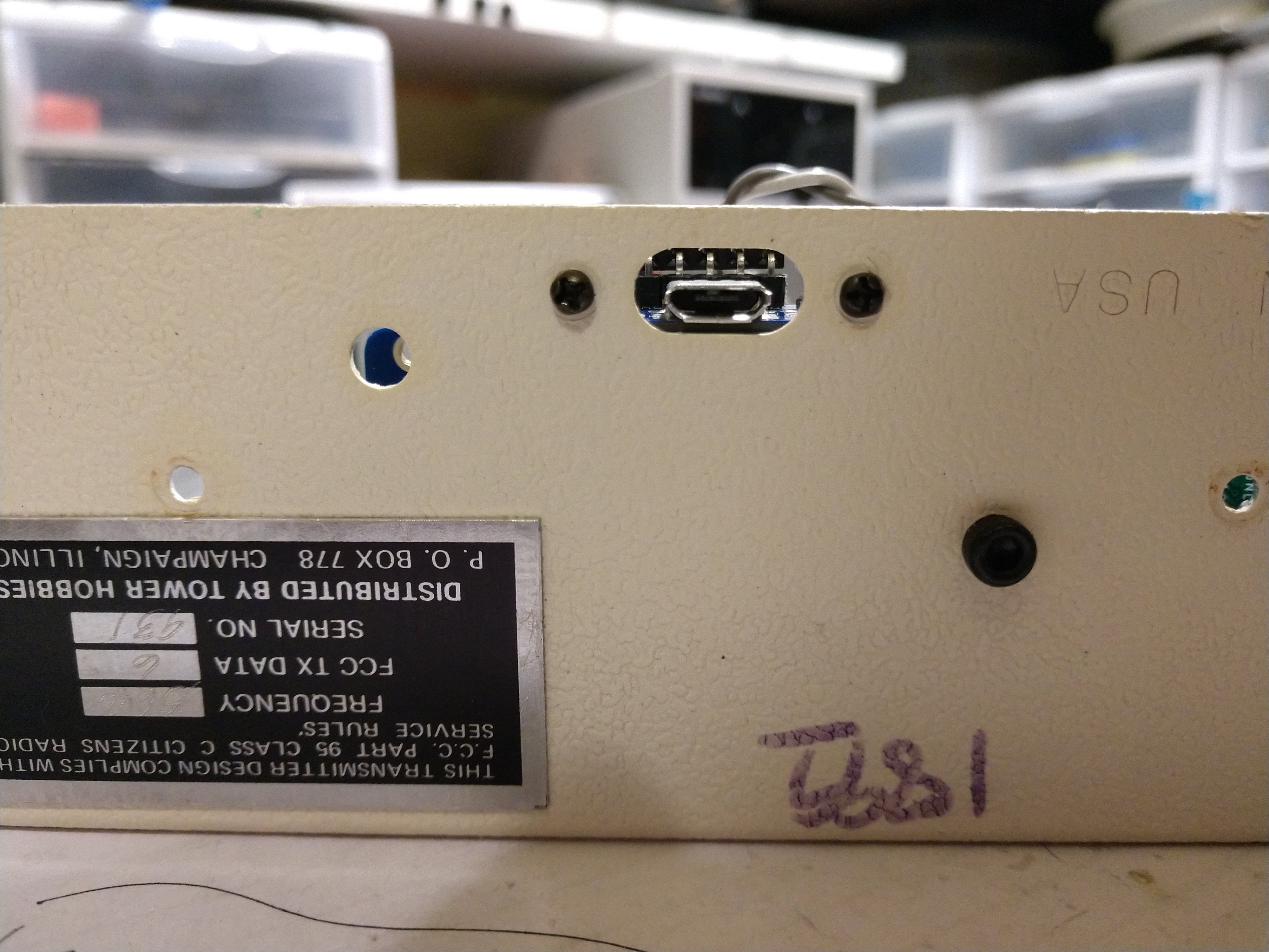
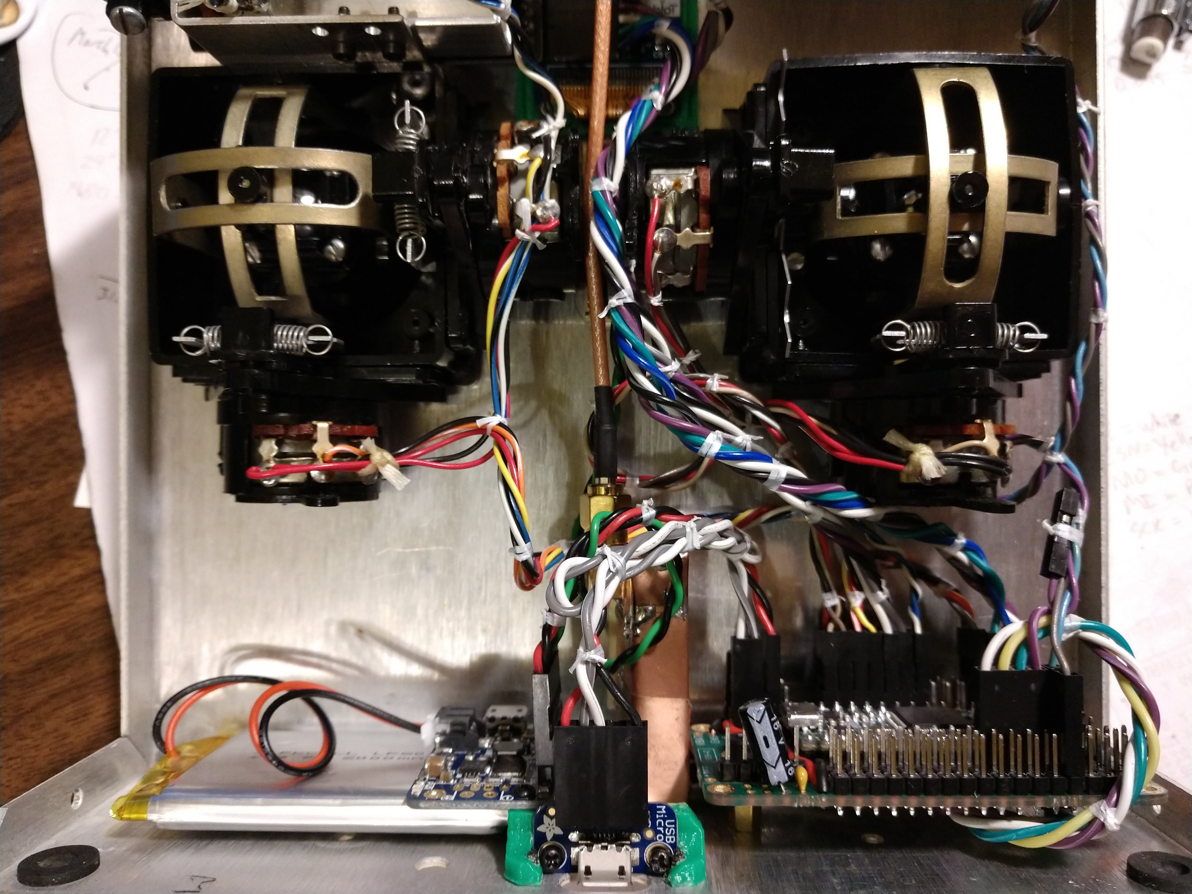
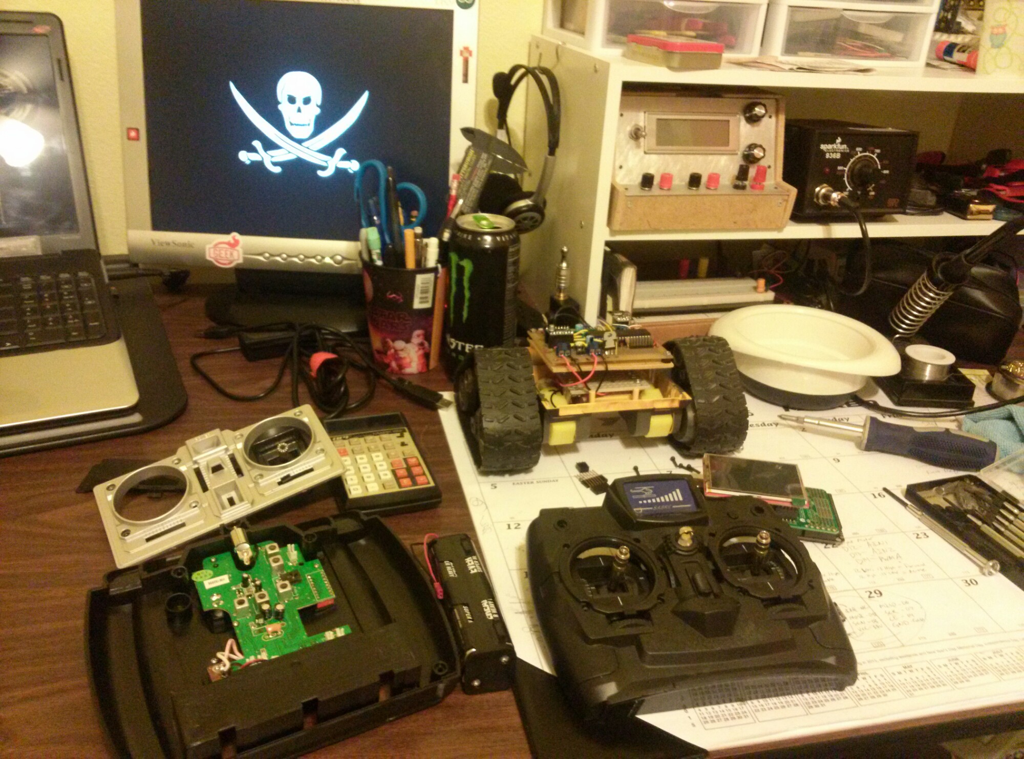
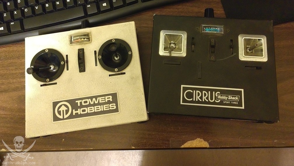
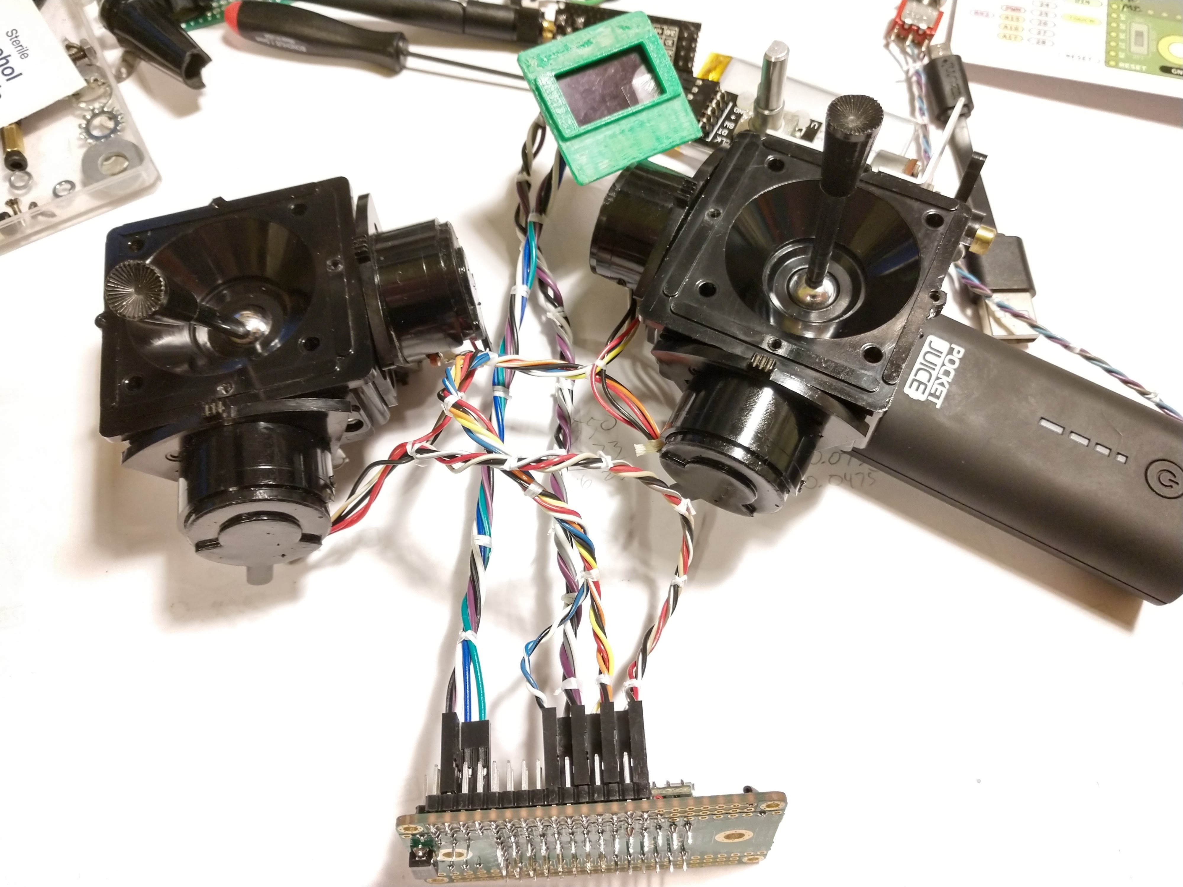
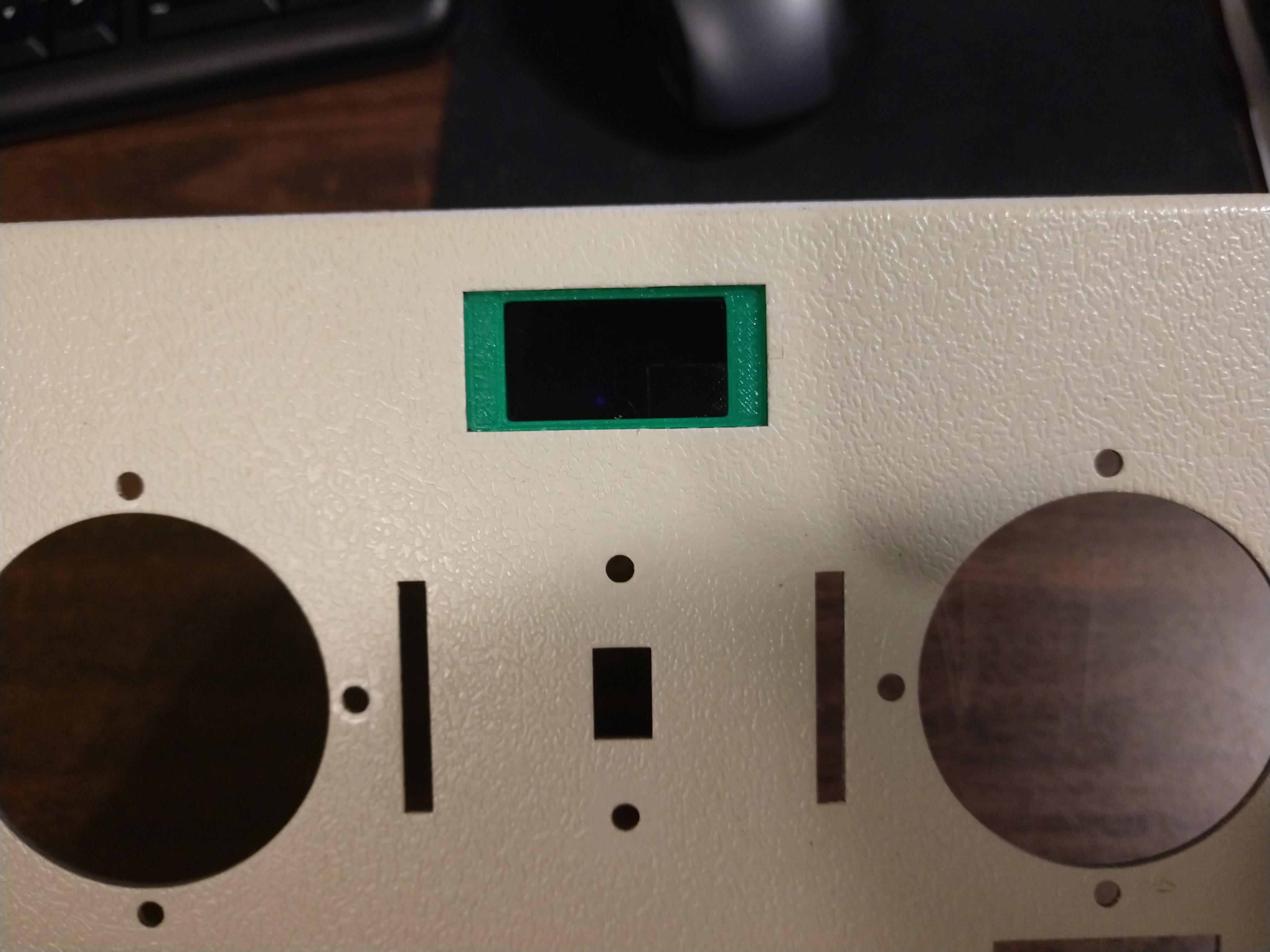
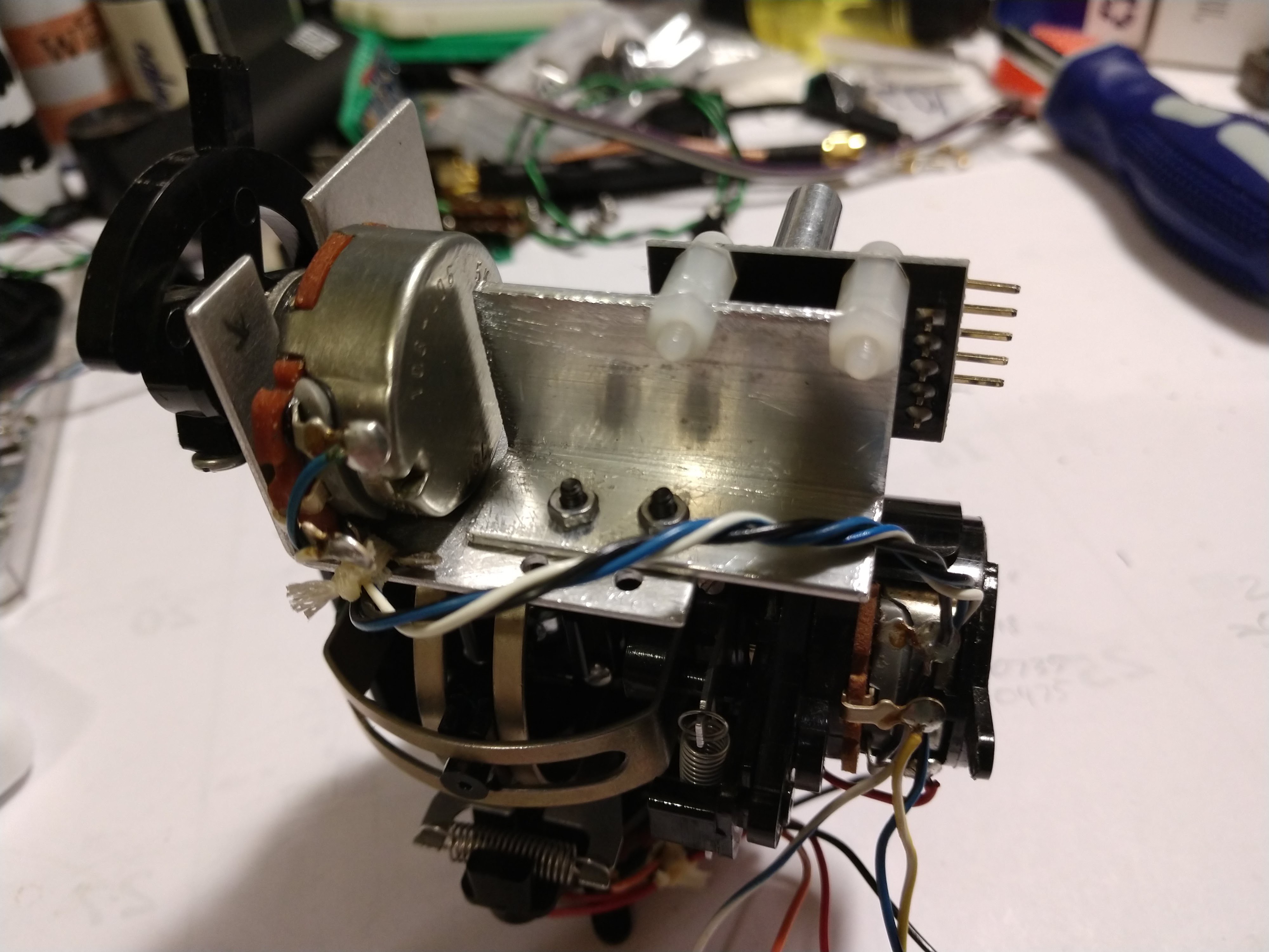
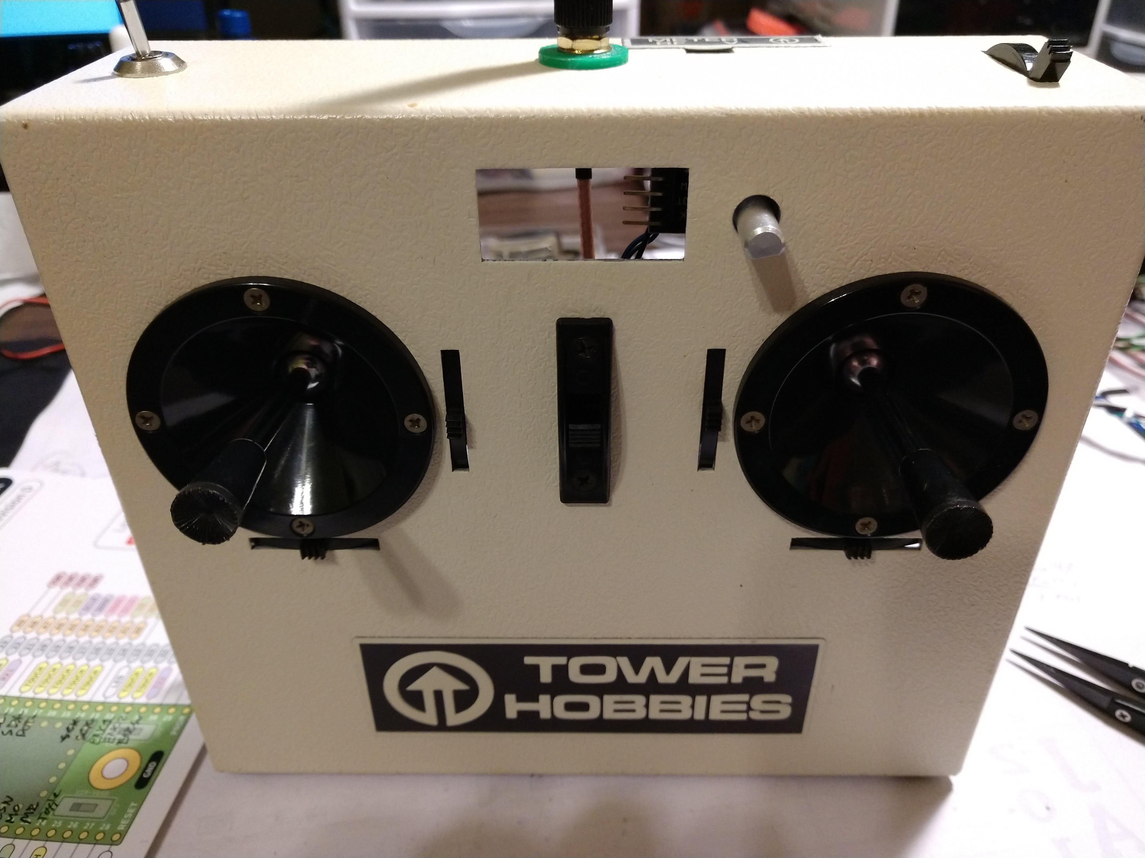
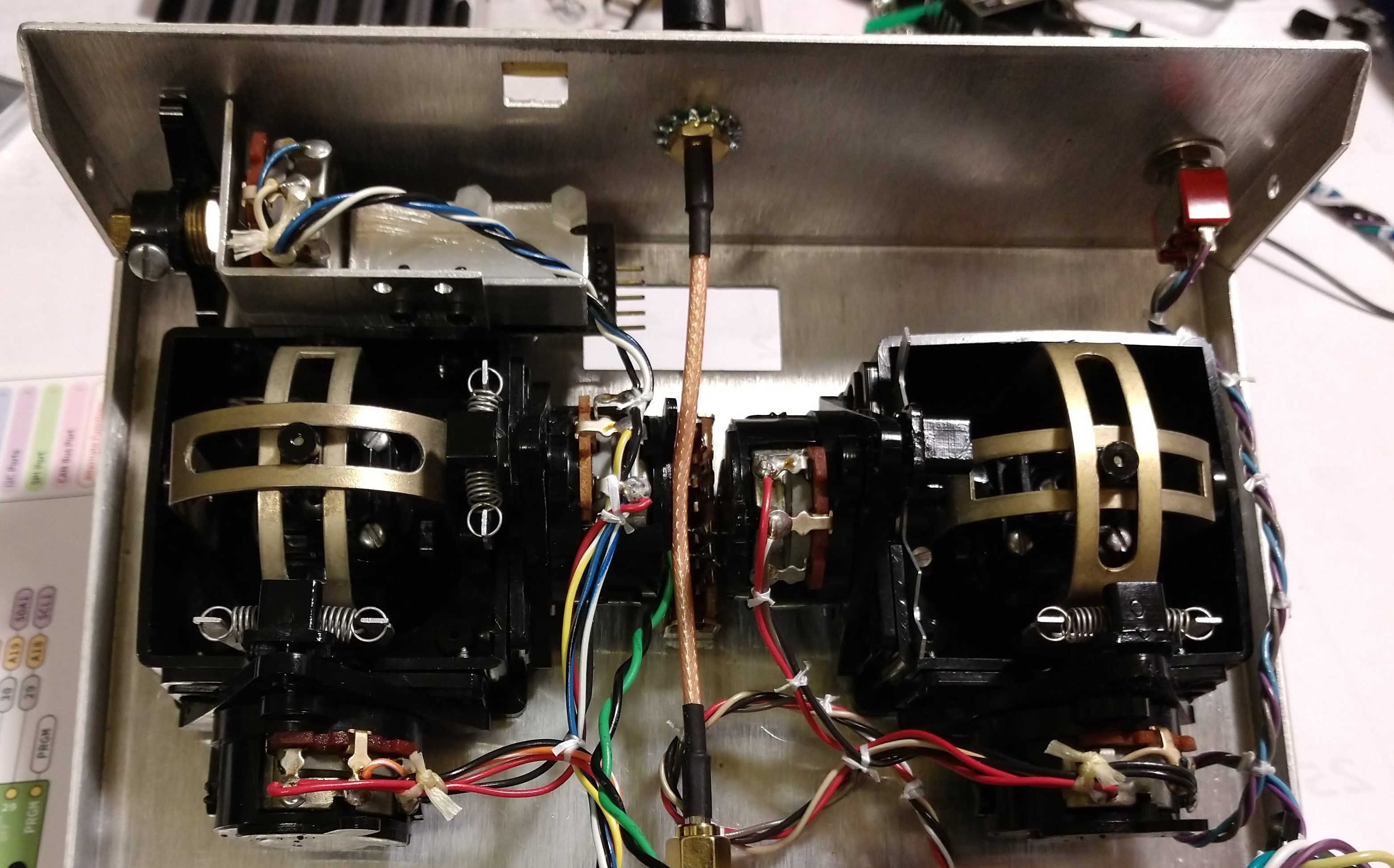
There are three basic parts to this project. The first is building the physical transmitter itself. This is the hacker/maker part of the project and can be accomplished in so many ways it's silly. You can buy gimbals and laser cut a housing to hold the parts, or duct tape them into a cardboard box. You can take apart an old Playstation controller and stuff the new electronics inside, or just pilfer the thumbsticks and put them in a plastic sandwich container (using duct tape if you like). Or purchase an old R/C transmitter from the thrift store, or a new one from the hobby shop, and use it to serve as the basis of the project and adapt its internals to fit up with the new electronics. Let your imagination guide you.
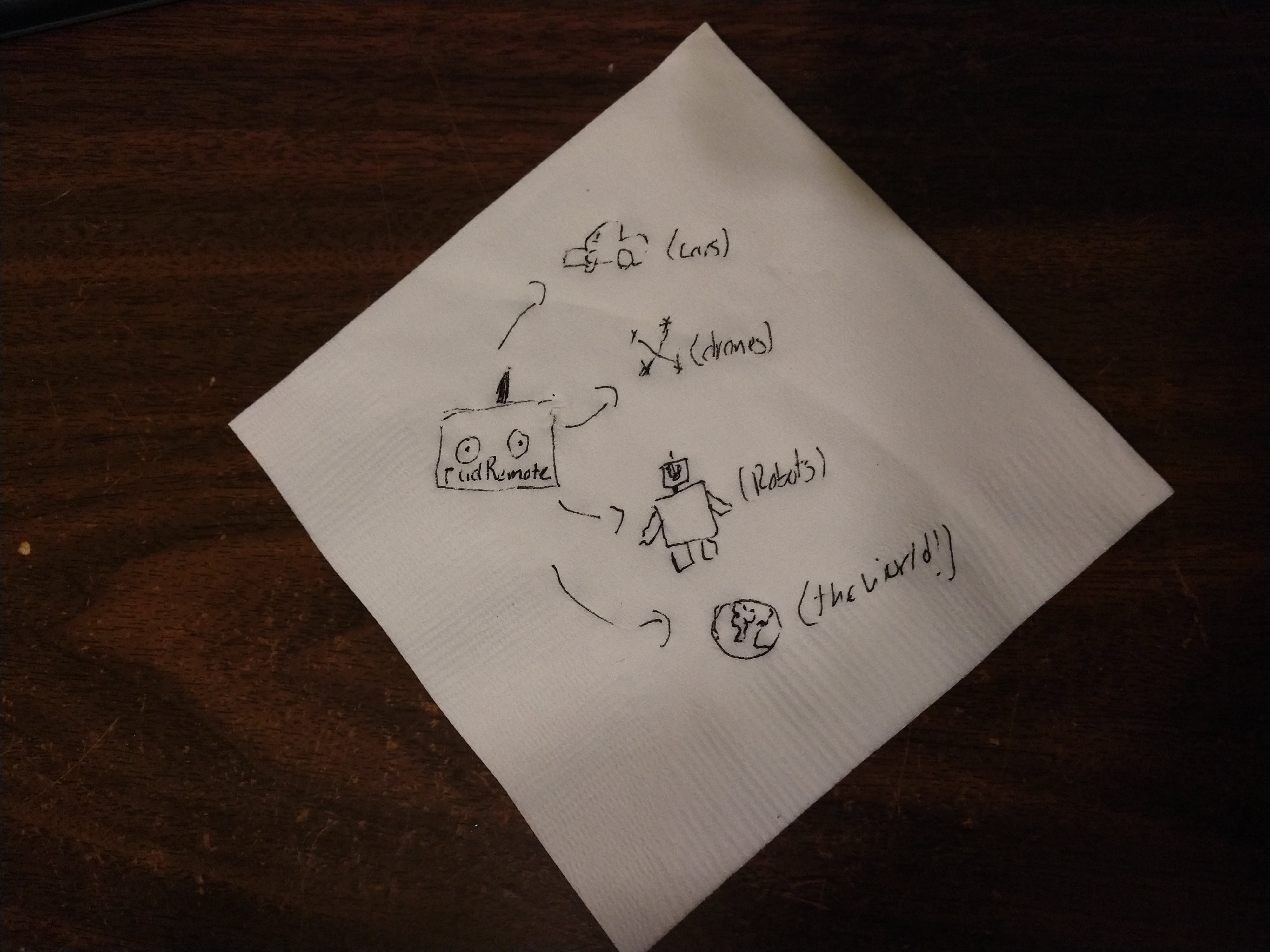
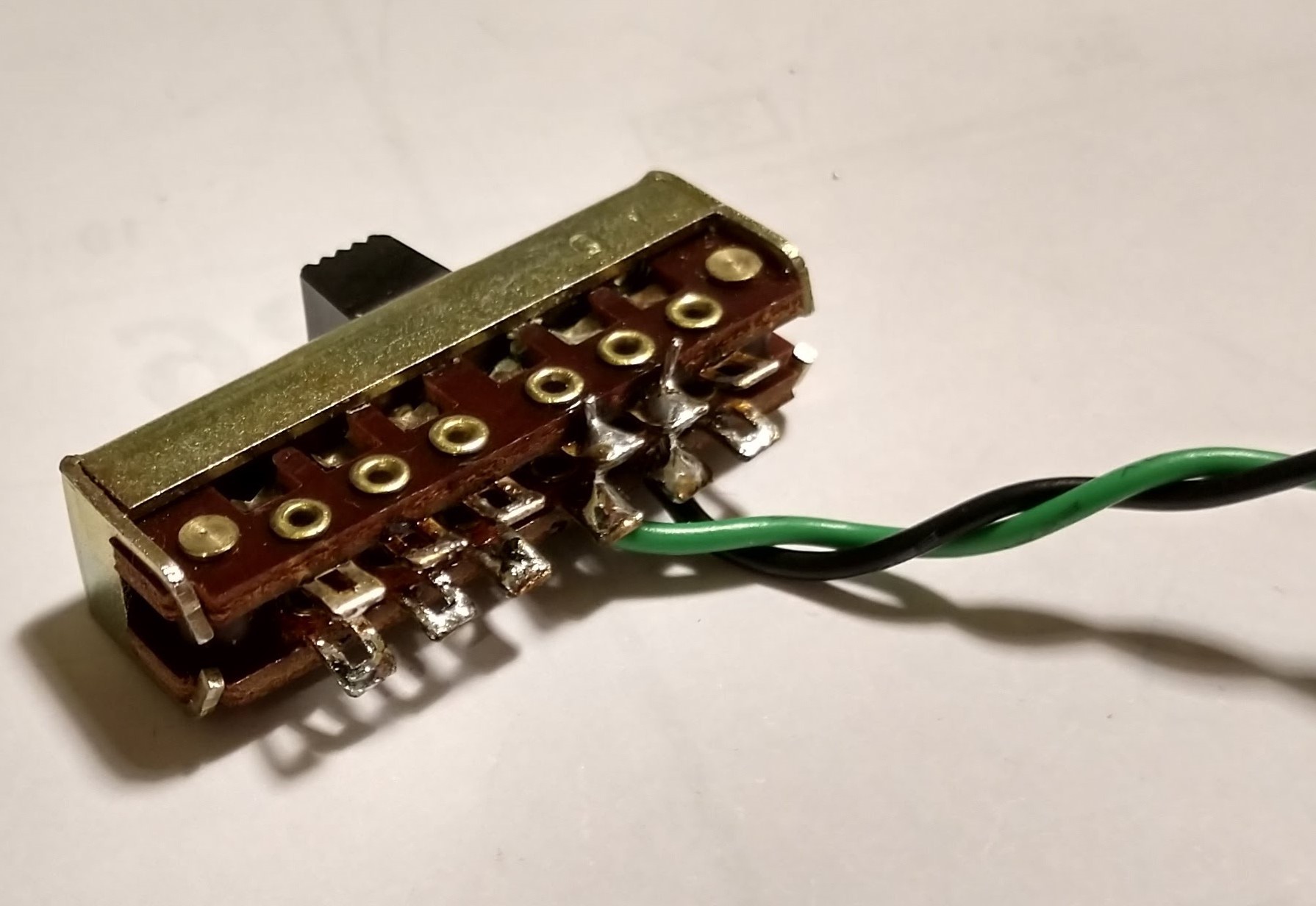
A transmitter that doesn't transmit anything isn't very useful. As such, the second part of this project is programming the microcontroller to speak out to the devices (quadcopters, robots, toy cars) you want to control. Since one of the devices I need this transmitter to control is a Crazyflie 2.0, making it speak CRTP seems a no-brainer. Even better, CRTP allows for up to 29 bytes of payload data, but the Crazyflie itself only uses 14 bytes. That leaves 15 bytes free to add other input, like buttons, toggle switches, or potentiometers.
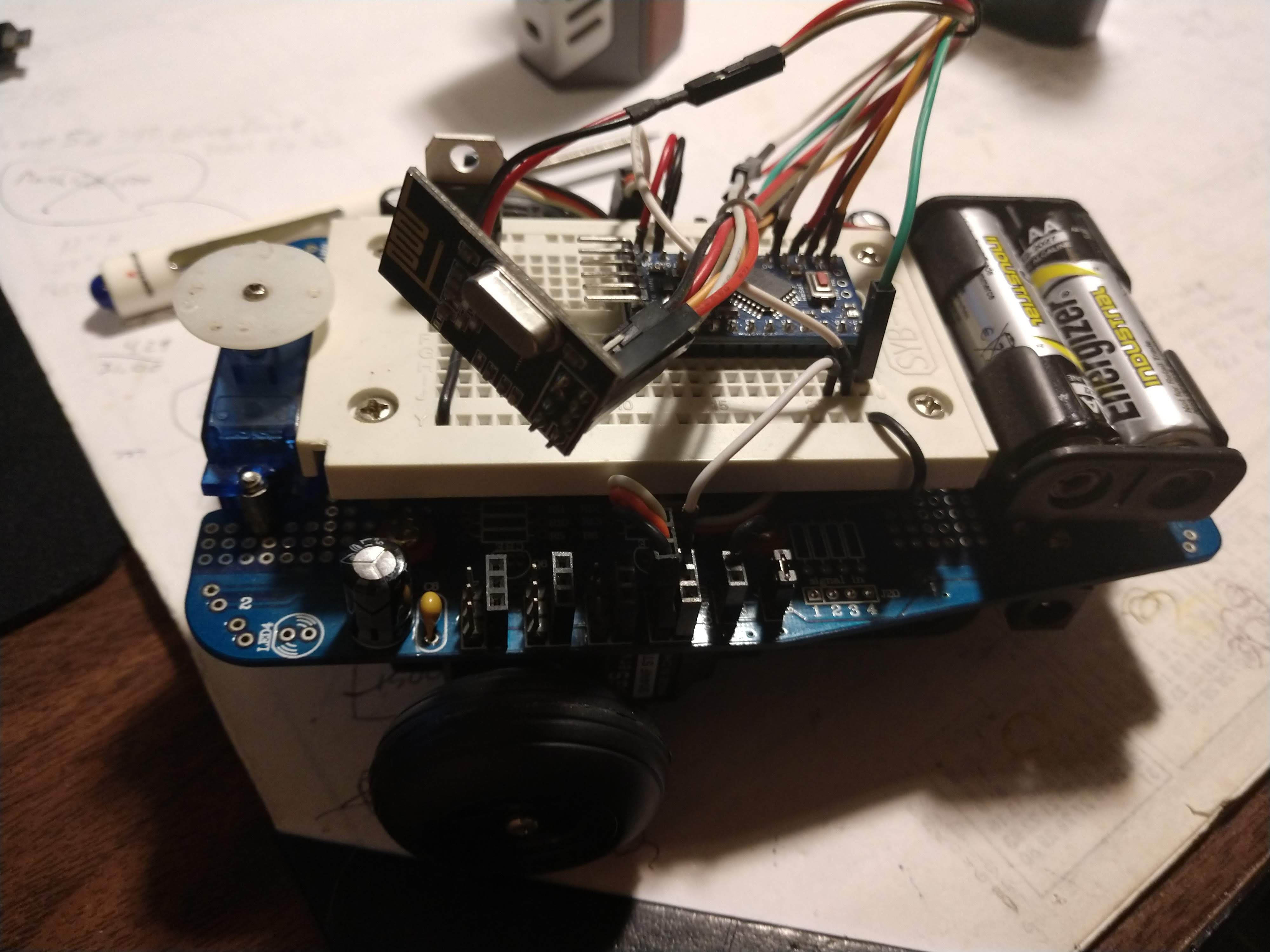
The final part of this project will be the receiver software needed to make these other devices work with rudRemote. As the radio is built around a readily-available NRF24L01+ module it is easy to add a hardware receiver to just about any microcontroller that speaks SPI. Then simply add the rudReceiver (name subject to change) code to your device's code, set the channel, and start receiving CRTP packets. How your device interprets and uses a packet of data is up to you. E.g. the first piece of data after the header is called "roll," but on a land-based driving robot roll could be used to signify "turn" instead, and "yaw" could instead be used to pan the camera.
Same thing we do every night: Try to take over the world!
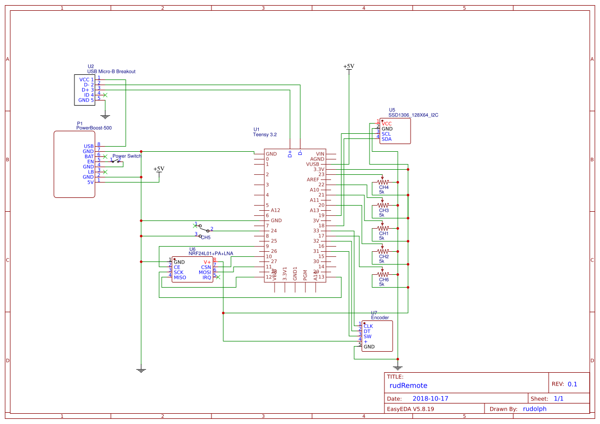
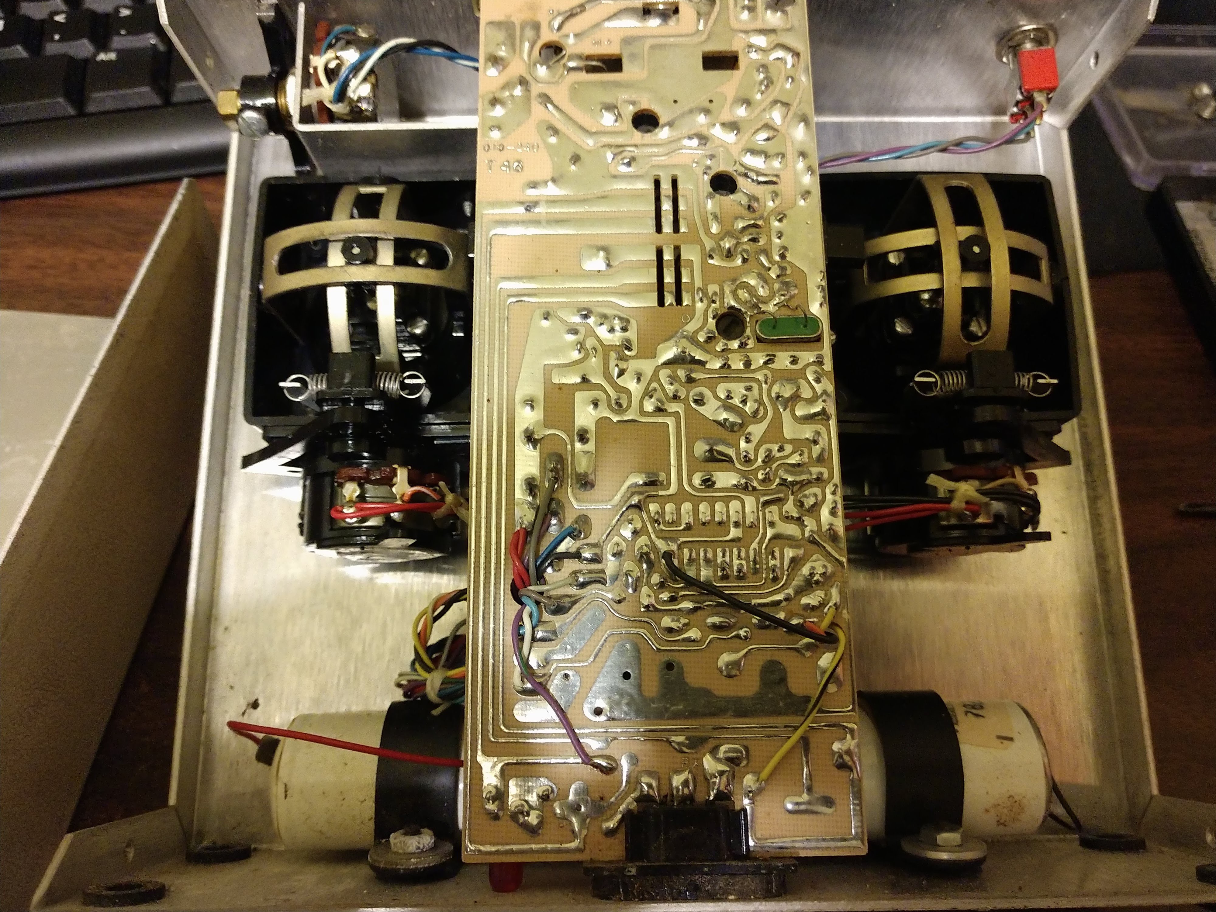
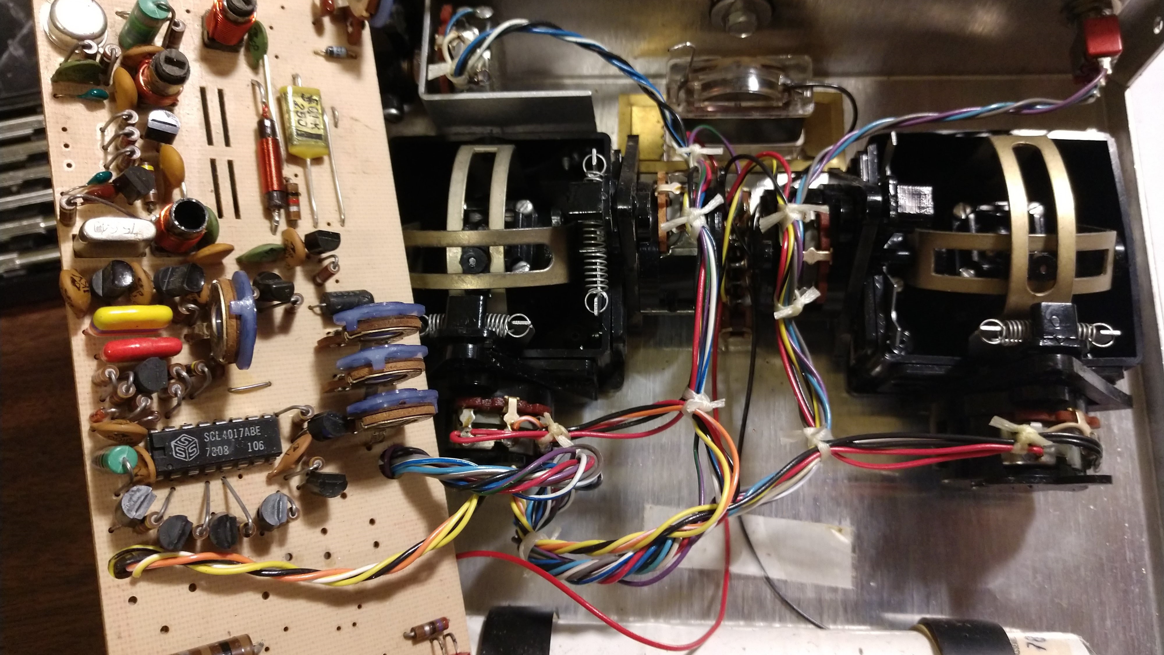
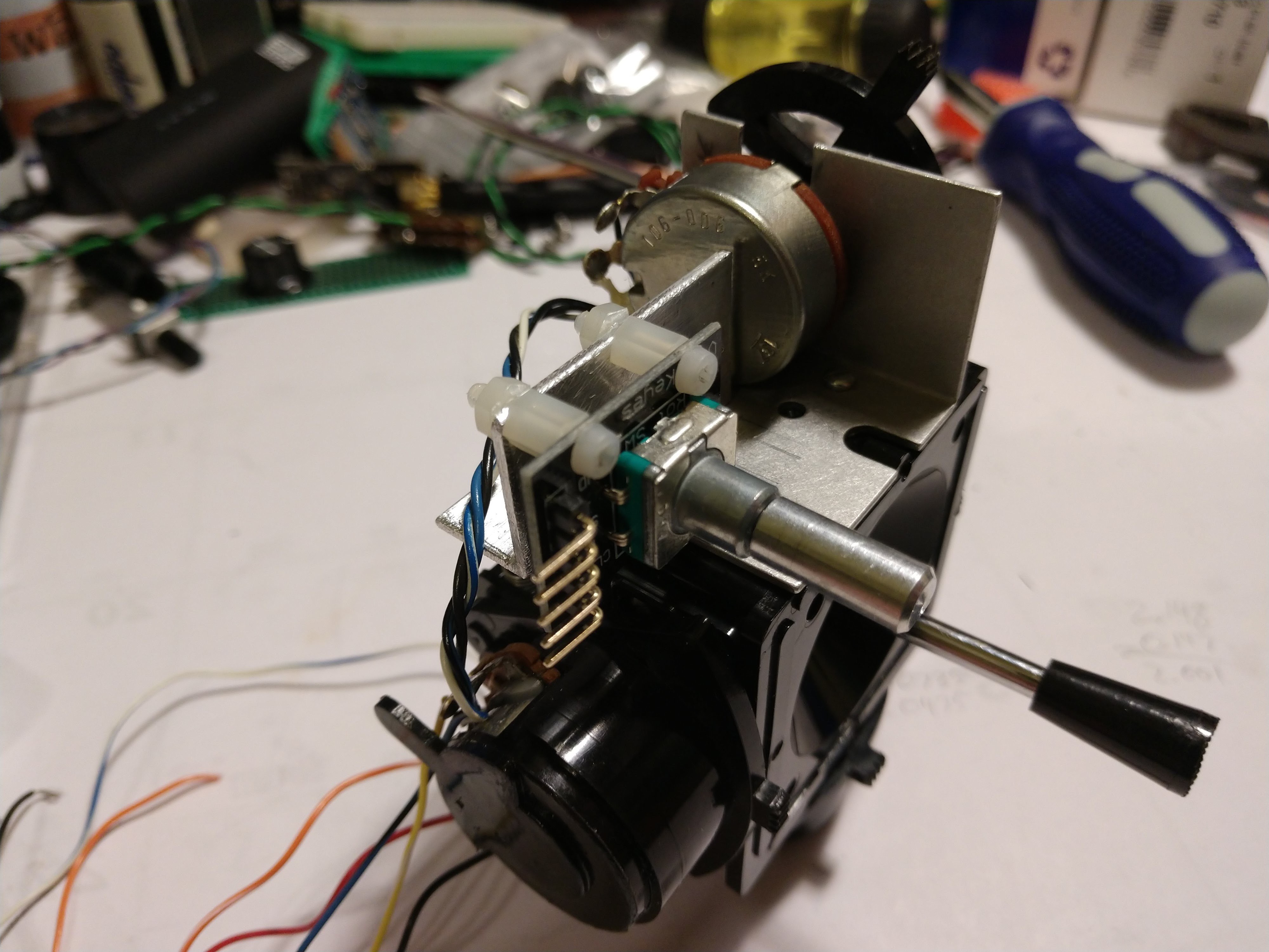
To be clear, this project is destructive to the donor transmitter. The controls will be interfaced directly to the I/O of a Teensy 3.2 rather than intercepting the data from the existing transmitter hardware. There are other methods of using old hardware to control modern hardware. See the links section for some of the inspiration for this project.
This is a DIY, hobby project that I am sharing as "here's what worked for me." I assume no liability for any damage or injury that may be caused by others' use of this project or software. The finished transmitter should not be used to control any flying model larger than a nano-quadcopter (e.g. the Crazyflie), especially anything fuel-powered (e.g. glow engine airplanes). Nor should it be used with any large land-based devices (e.g. lawnmowers, automobiles, etc...) or anything that might be potentially dangerous to any living thing.
 Mike
Mike
 Non-ICE
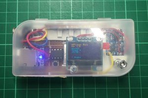
 AccidentalRebel