 Roger
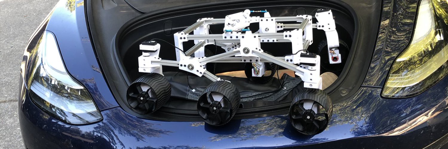
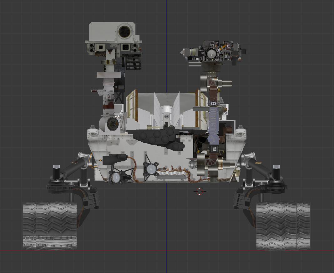
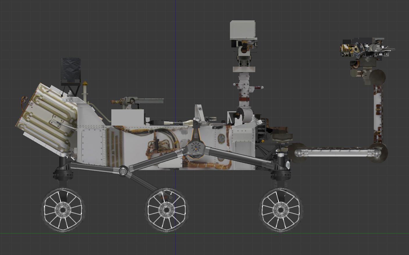
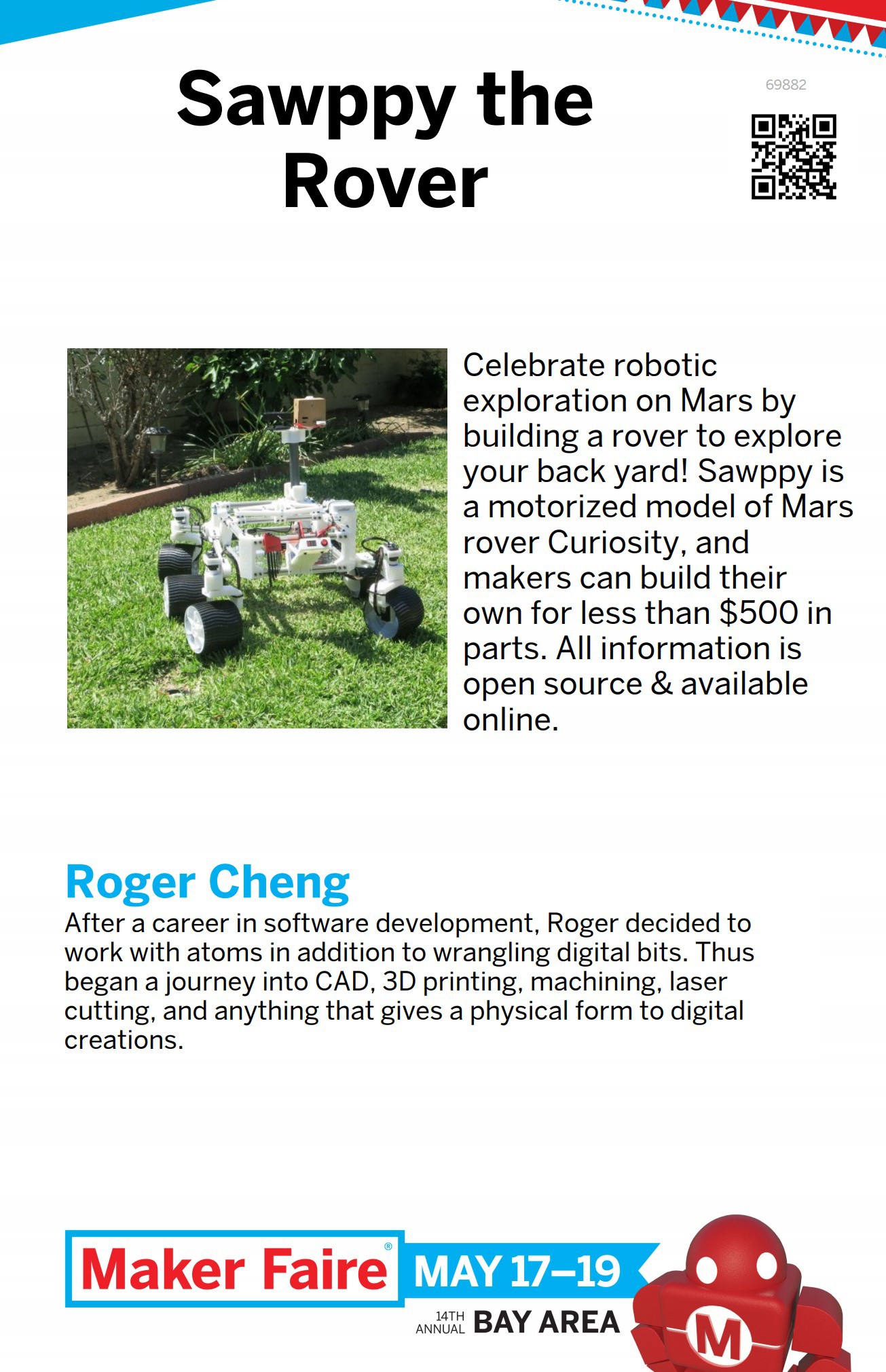
RogerSawppy the Rover was inspired by JPL's Open Source Rover project. Most of the differences between Sawppy and its JPL inspiration were motivated by a desire to reduce cost and complexity. JPL's rover is designed for education, to be assembled by a school team and give a robust foundation for structured curriculum. Sawppy is more suited for individual hobbyists like myself who are happy to tinker and willing to make some trade-offs to lower cost.
The budget was $500, and getting there required the following changes:
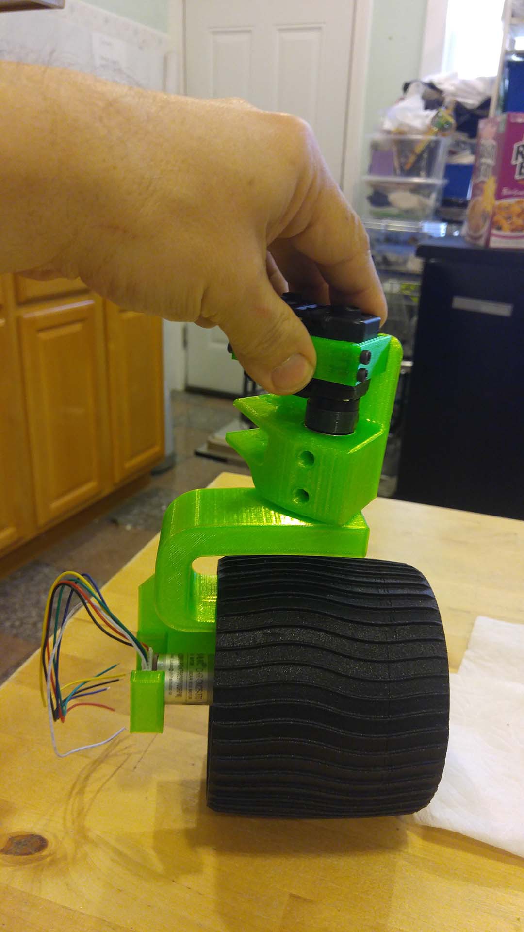
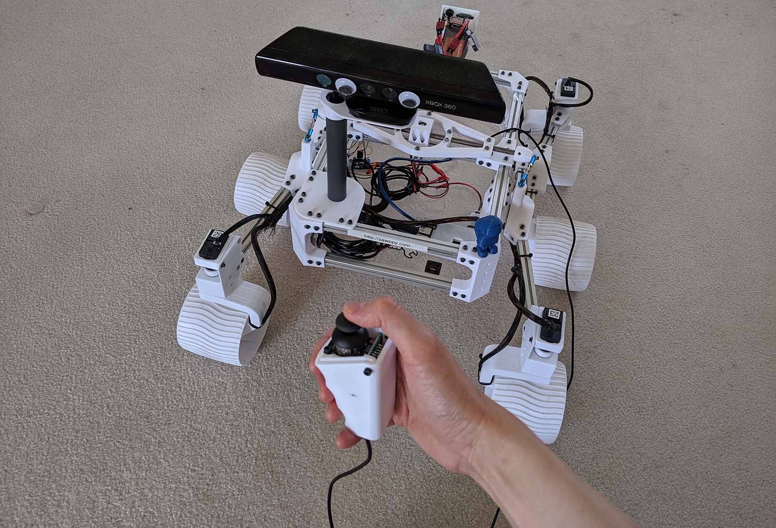
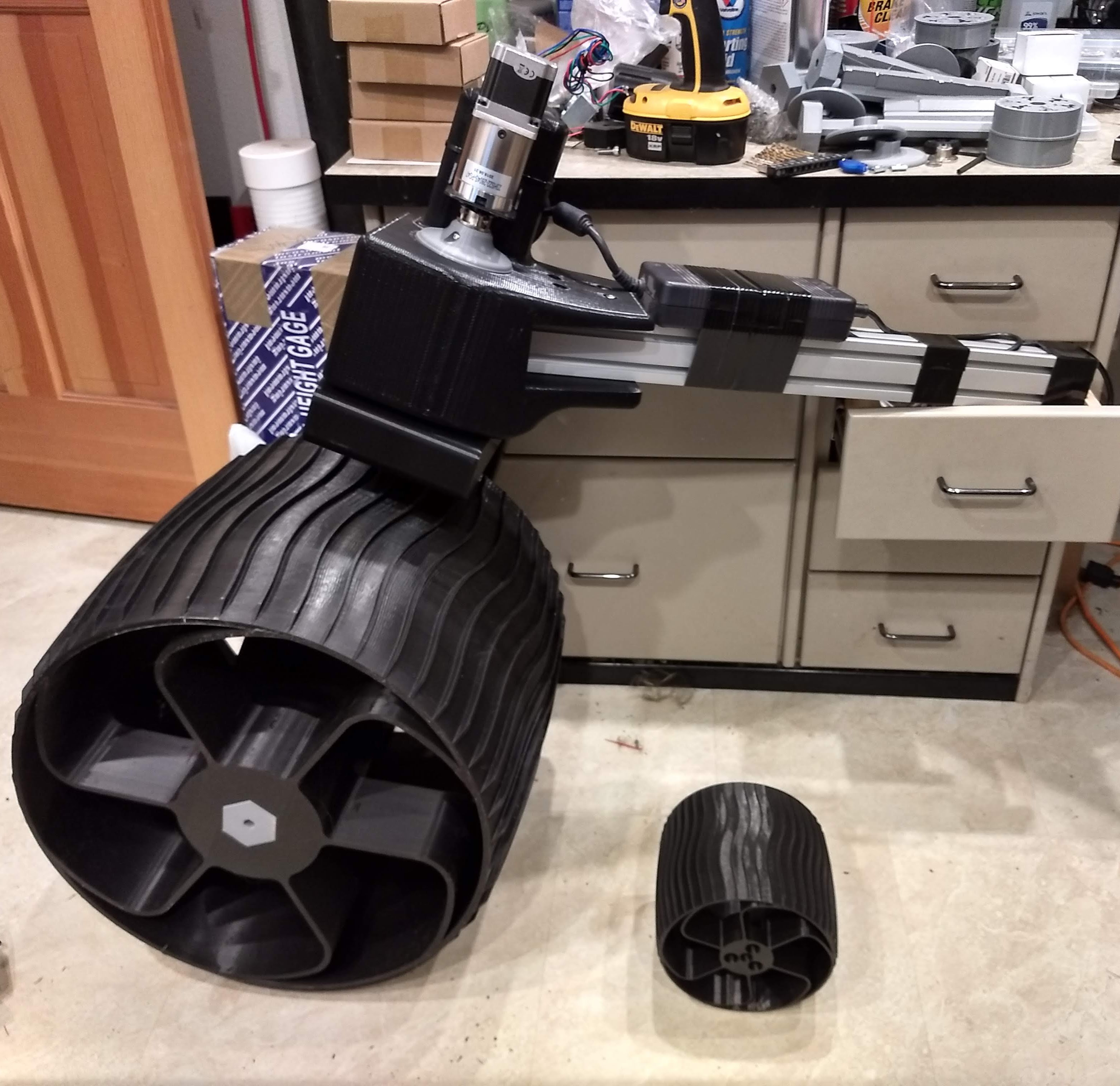
- Motorization: Instead of using gearmotors with encoders managed by RoboClaw motor controllers, moving the wheels will be done with serial bus servo motors.
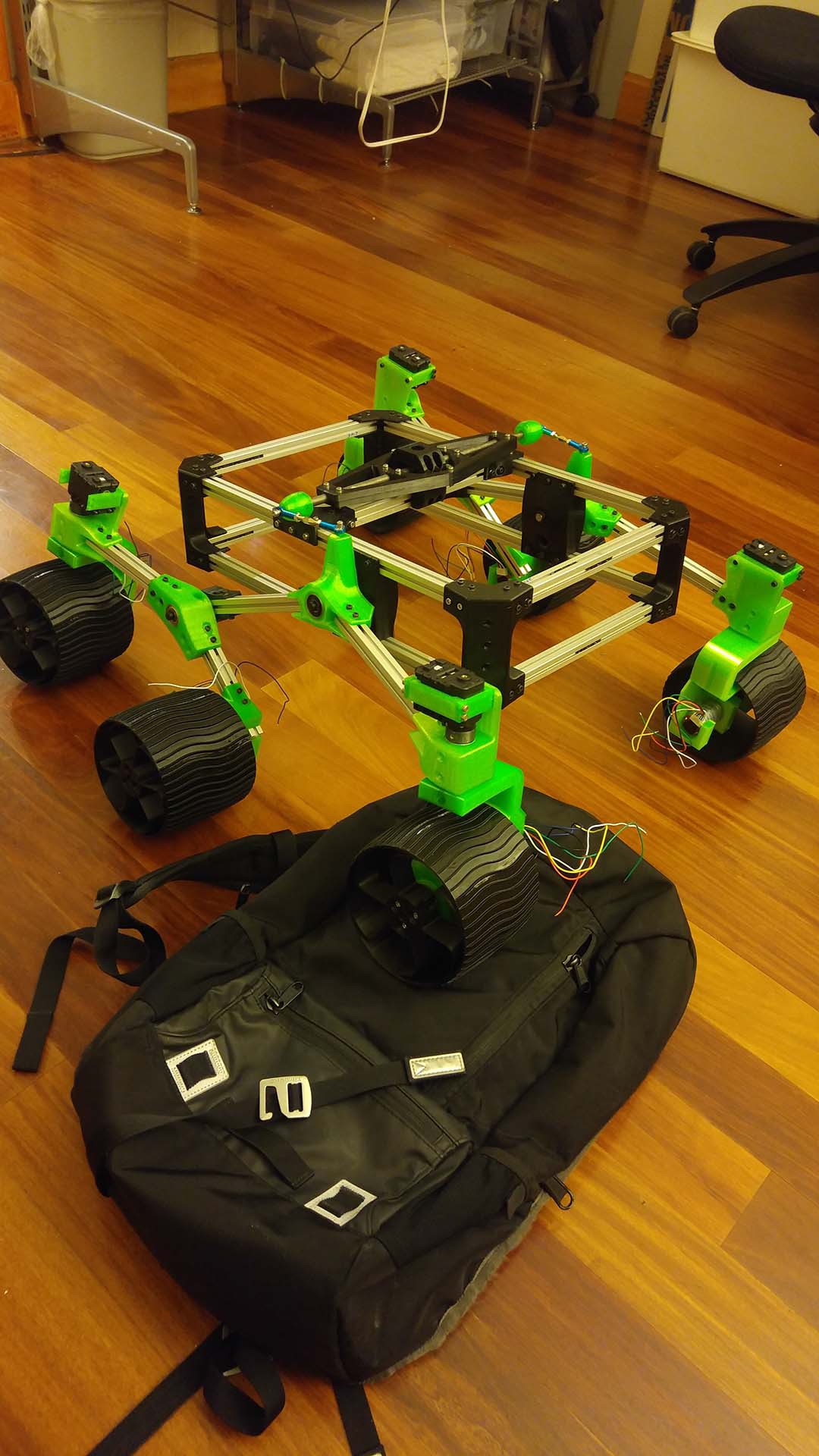
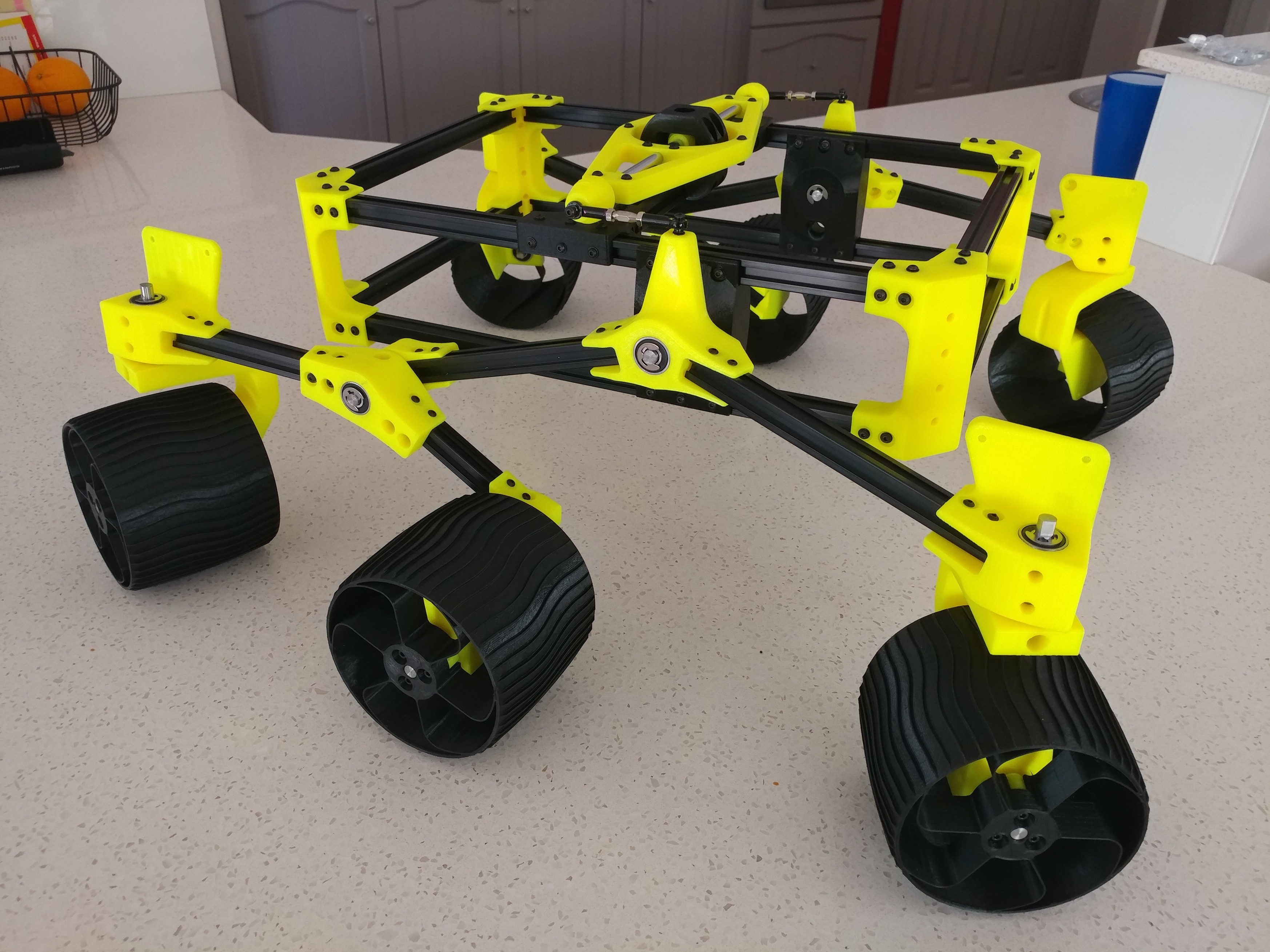
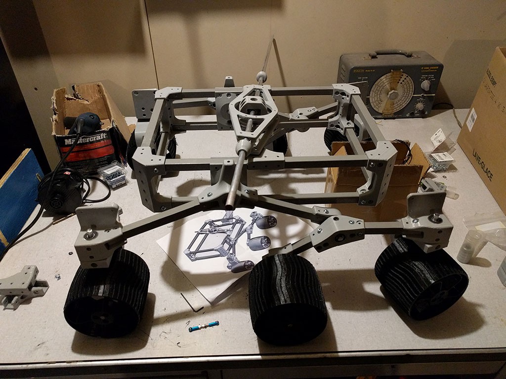
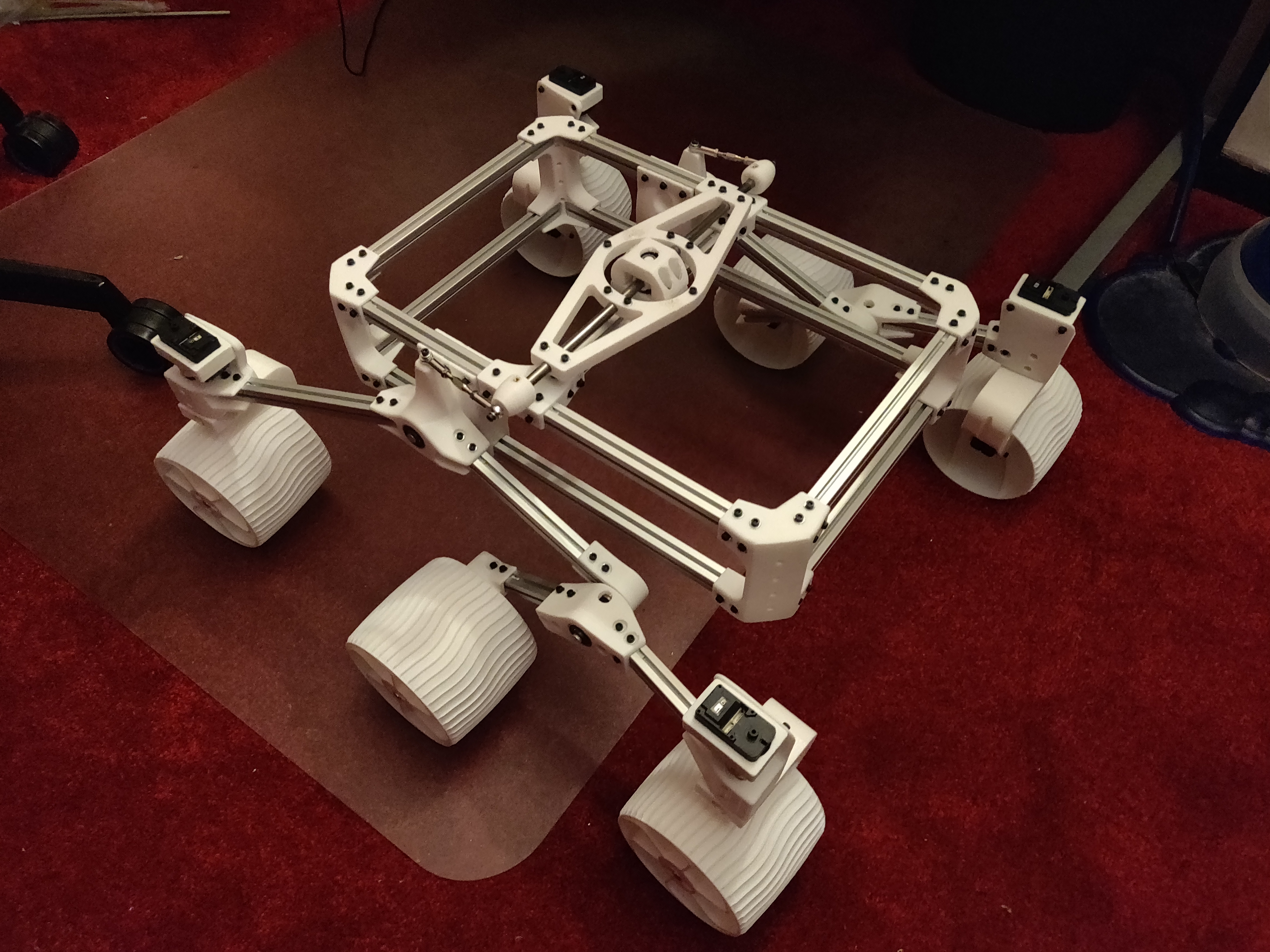
- Construction Method: Instead of using the Actobotics construction system, Sawppy will be built from Misumi 15mm 3-series aluminum extrusions beams connected by 3D-printed plastic parts.
These two major design goals can be summarized as: Servo Actuated Wheels, Printed Interconnect For Extrusion. The acronym SAWPIFE led to the nickname "Sawppy".
See the "Links" section for pointers to additional information:
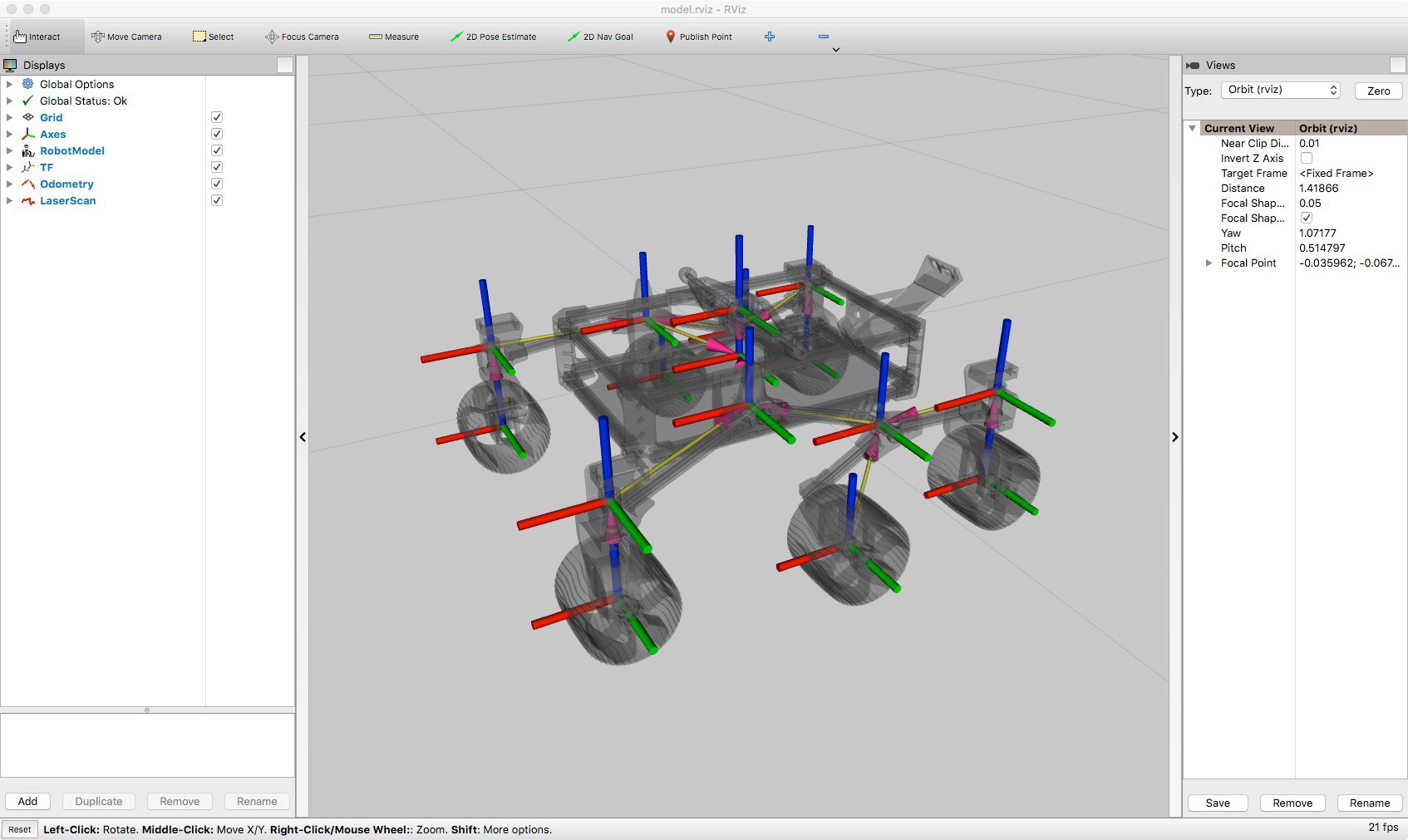
- Live Onshape CAD file: This is where I'm tweaking and building Sawppy in full public view. Be warned the live file has upsides (latest ideas!) and downsides (latest idea doesn't work!)
- Github: This is where the assembly instructions currently live. It also has a snapshot of Sawppy components in STL file format. These parts may lag behind the live CAD data, but they have been printed, installed, and proven to work on my rover.
- Build Blog: The history of Sawppy, including stories of design goals and lessons learned from failures.
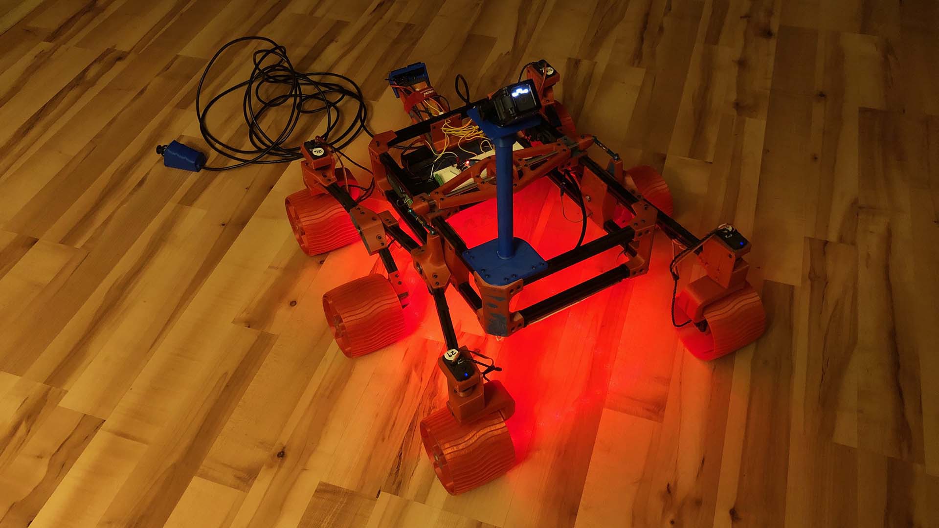
Since the time I declared Sawppy version 1.0 (mechanical foundation) complete and posted assembly instructions, others have built on top of what I've released to the world! They're outlined in the project log "Sawppy Builders" entries, page 1 and page 2 with more to come as I hear about more rovers.


 Kaspar Emanuel
 Steve Pendergrast
 ben.phenoptix
 Joan Horvath
Hello! I am building Swappy and it has been great; I've learned a lot. I am having some issues with the software, however. I am using the modified SGVHAK software, as recommended. Although things were going well until start flask with python 3, at this point I began to have issues, and after consulting a friend, I switched to python 2.7, only to have trouble installing the virtual environment and getting several error messages. I am at a standstill and am not sure how to move forward. Can you recommend a way to proceed? Thank you very much!