 ptrav
ptravMy PCBs from Allpcb.com and the components have arrived a while ago, but I had to delay the assembly due to some unrelated stuff.
Finally the assembly have started.
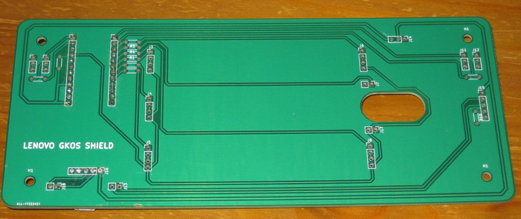
The PCBs are in excellent condition -- AllPCB quality, as always, very good:
The final wiring diagram is as following:
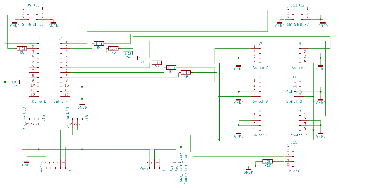
I preferred this method over constantly shining LEDs on the photo-transistors, as only one LED is lit at the time, thus the LED power consumption is 2 mA instead of 12.
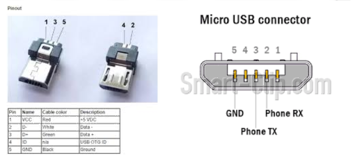
In the original PCB I made a mistake wiring 5V to the Arduino directly and not through the USB port. It was discovered that without 5V on the USB pin 1 Arduino Micro Pro does not connect to the PC. I fixed this by soldering the 5V wire to the board and cutting the trace to Arduino pin.
Another minor issue was the power switch position, which was too far from the PCB edge. I fixed it by adding some extra wires to the switch.
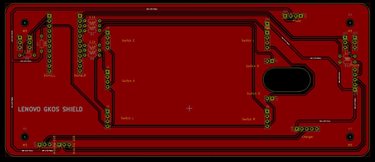
The updated PCB version:
Discussions
Become a Hackaday.io Member
Create an account to leave a comment. Already have an account? Log In.