Close
0%
0%

ros-omni-base

ROS mobile robot base for everyone

Public Chat
Similar projects worth following
An ongoing project aiming to make and, most importantly, document a robot base to be used with Robotics Operating System.

When it comes to ROS compatible robot bases, the most documented and DIY-friendly one is currently Linorobot. The base we'll build is essentially an implementation of Linorobot-compatible base.

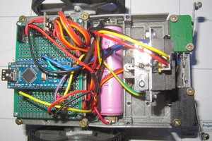
What me and my teammates are building and sharing here is essentially a concrete implementation of Linorobot base - after all, standing on the shoulders of giants is the way to even greater accomplishments.

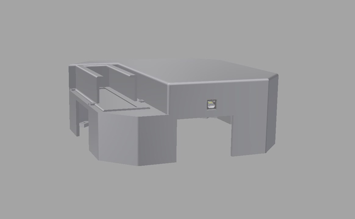
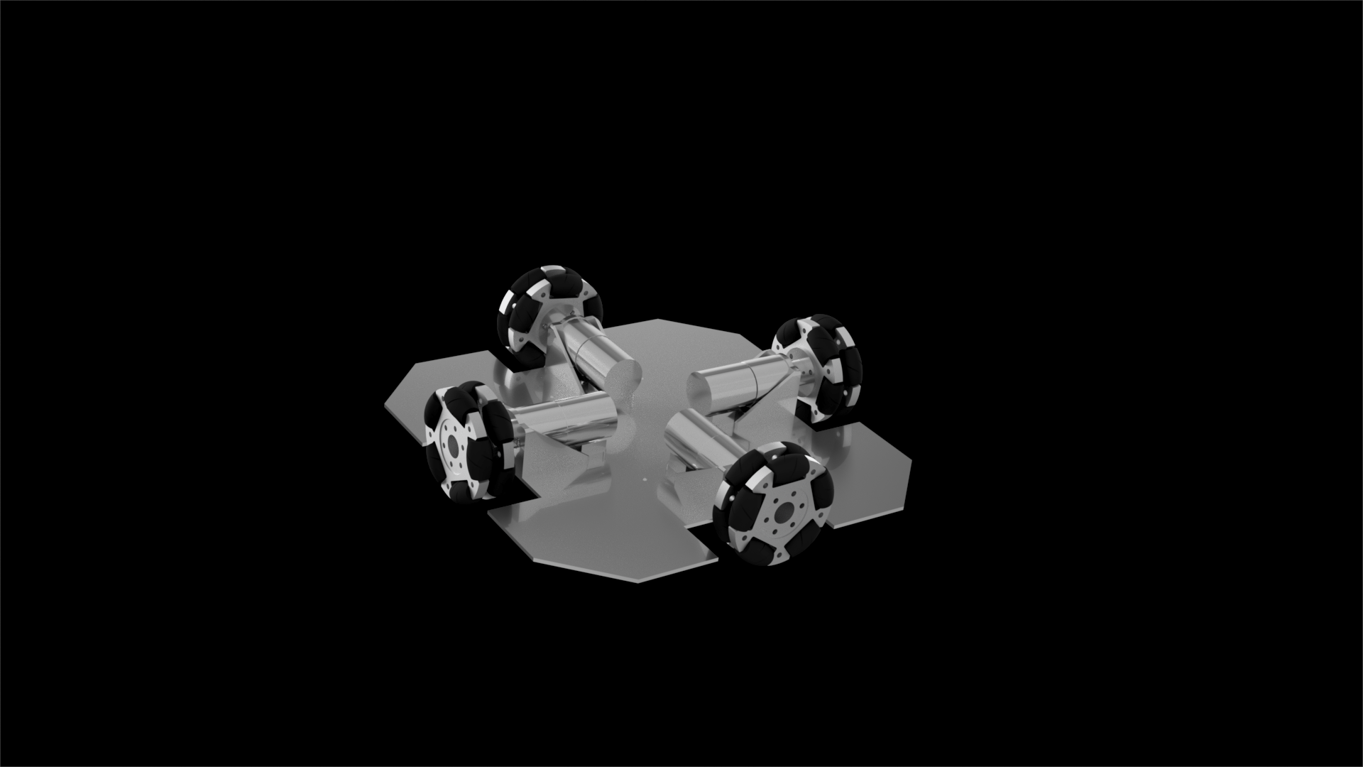
ros-omni-base is only the wheeled platform for Linorobot, which is a complete firmware-software-electronics bundle for any robot base with wheels, Linux board and Lidar or Kinect to sense the surroundings.

This project is meant to aid beginners in robotics with the following:

  • Reducing the cost of entering robotics with ROS. Instead of buying Turtlebot, you can make your own.
  • ros-omni-base eliminates the uncertainty still associated with building Linorobot from scratch. Linorobot software can control two- and four-wheeled platforms, including Ackermann steering and Mecanum wheels - provided it's loaded with the right firmware, but it doesn't include BOMs, drawings, assembly instructions etc. I think this decision was made intentionally to signify the fact that Linorobot is mostly mechanics-agnostic, but it usually brings more confusion for newbies. ros-omni-base is built upon a concrete set of components.
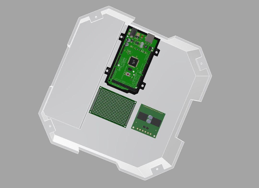
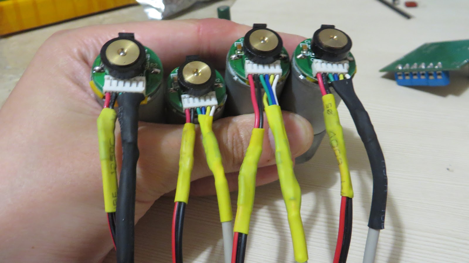
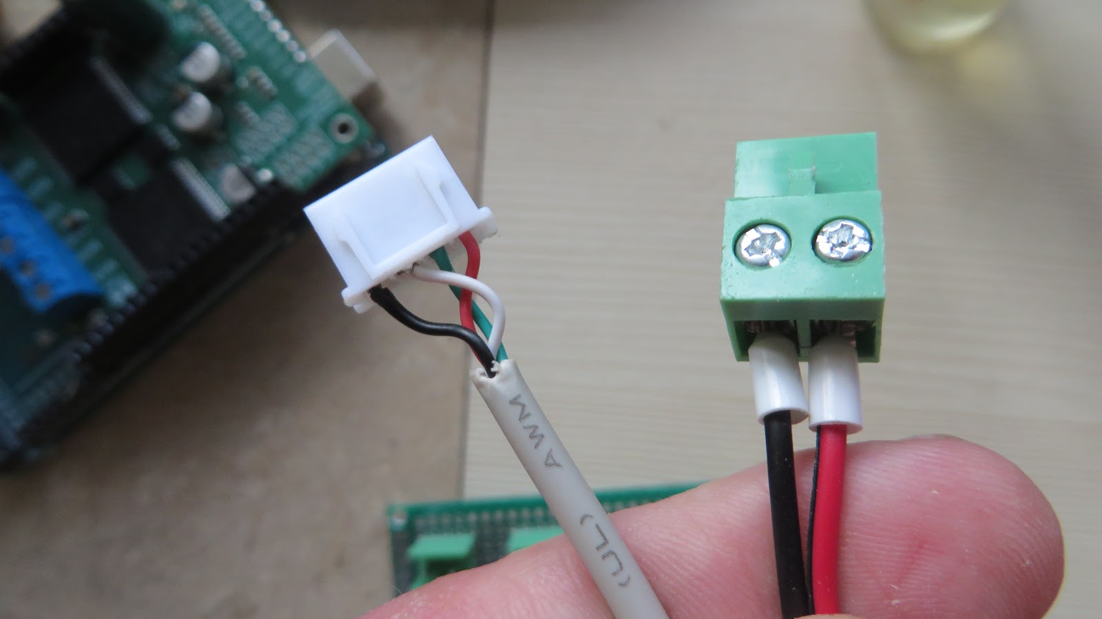
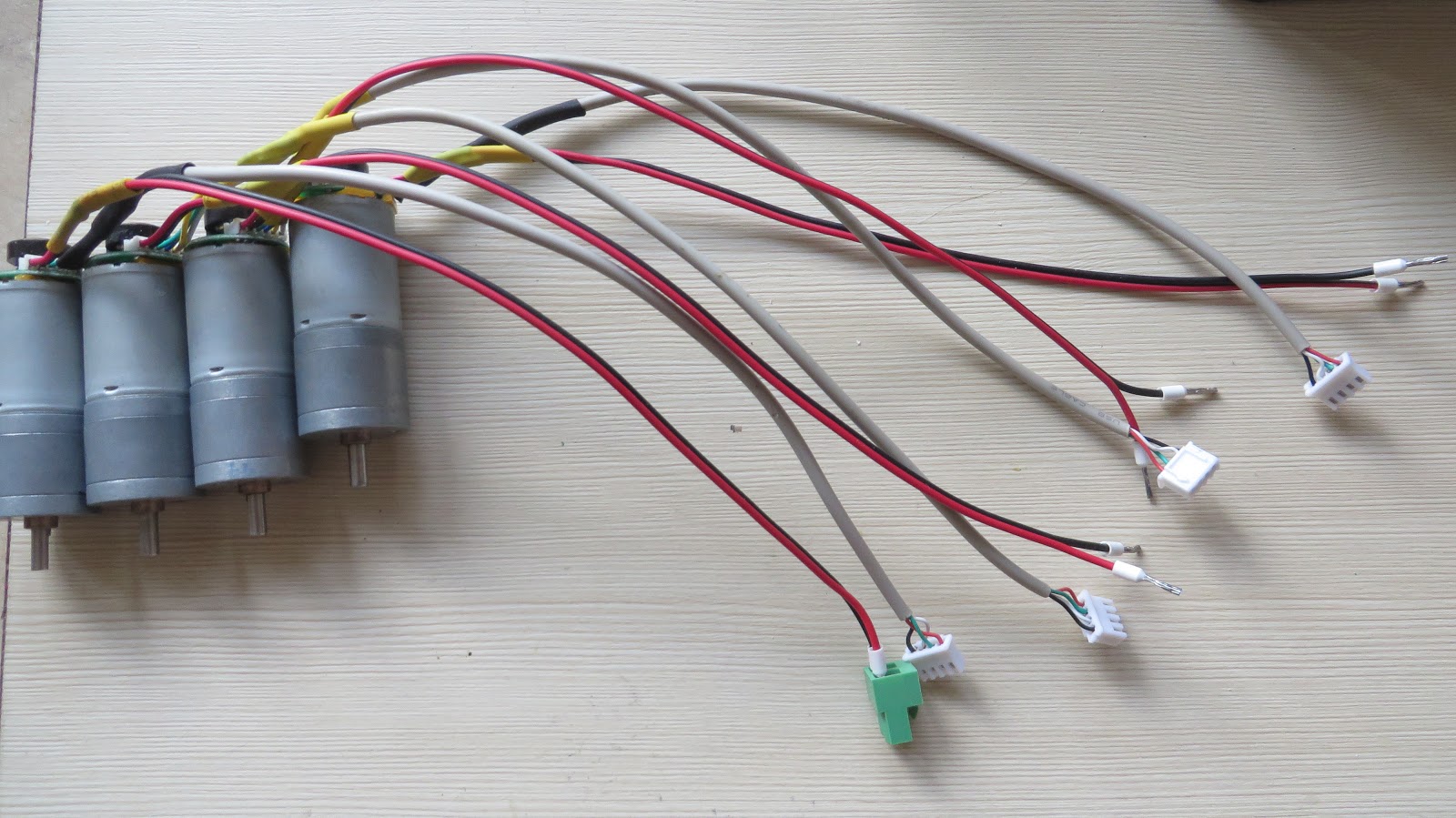
  • Cheaper and more widespread Arduino Mega instead of Teensy to control motors and read encoders. The aim of this swap is to make part location process as easy on your mind and wallet as possible, without compromising performance at the same time.
  • As an upshot, quickly get you up and running with robotics and ROS.

The end result you're supposed to get after following this guide is a wheeled robot base that can be connected to ROS with USB and controlled via teleoperation (standard Twist messages) using teleop_twist_keyboard package.

ros_omni_base_kicad.zip

Full Kicad schematic, including PDF and JPG render.

x-zip-compressed - 421.03 kB - 06/04/2018 at 10:24

Download

View all 12 components

  • Dome modeling update

    panovvv06/04/2018 at 10:01 0 comments

    Here's the dome that's supposed to cover the aluminum plate and house the whole assembly. The thing is, it's way too big for printing. Battery holder can be (and already is) printed separately, but separating the dome itself into printable parts is still work in progress.

  • Deadline

    panovvv06/04/2018 at 06:34 0 comments

    With Hackaday Prize 2k18 deadline approaching, I'd like to recap what's been done during the month:

    • Mechanics: base modeling is 90% finished. The aluminum base has been cut out, and small details like motor holders are already printed and fitted, but we still haven't figured out how to print the huge plastic dome atop the aluminum base that's housing the electronics.
    • Electronics: the schematics is ready, soldering is postponed until the dome is ready, so that the assembly and soldering may happen in-place.
    • Programming: it's been decided to reuse the existing firmware to the max, so this base will be compatible with Linorobot.

    What's left to do:

    • Mechanics: somehow splitting the huge dome and printing it, assembling the base and screwing on the electronics.
    • Electronics: soldering the whole thing together according to the schematics.
    • Programming: appropriating Linorobot firmware to make use of Arduino Mega's pin change interrupts to read encoder signals (2 encoders can be used with already existing, normal interrupt-based encoder library) and different model of IMU.

View all 2 project logs

  • 1
    Mechanics: Motors

    Before installing the motors, I suggest filling the gap between motors and hall sensor board with something soft and dielectric, like silicon or rubber, because the board is only held by 2 fragile terminals that will eventually break off due to mechanical stress

  • 2
    Electronics: replacing motor's wires, fitting them with connectors that match distribution board.

    The wire that comes with motors was way too short, so I replaced it with the longer one, replacing the flimsy 6-pin connector with separate connector for power (motor wires) and signals (encoder wires).

    • Crop off the existing wires first. To see which color corresponds to which wire, see table on motor's product page.
    • We are going to separate signal and power lines on this motor. This

    is actually the best practice in electronics engineering because it minimizes crosstalk between them. Solder a longer wire to red and black wires and insulate them with heat shrink.

    • Let's lengthen the encoder's wires now. There's 4 wires total, 2 of

    them signal and 2 power wires. Now, which insanely popular cable fits the bill? USB - everyone these days has at least one in their house! Butcher any cable you don't want for perfect pieces of 4-wire cable.

    • The opposite ends of motor's cables will need wire-to-board connectors.

    That's what the result should look like:

  • 3
    Mechanics: assemble the robot base

    As the end result you're supposed to get a wheeled platform that will look like this:

View all 5 instructions

Enjoy this project?

Share

Discussions

Similar Projects

Does this project spark your interest?

Become a member to follow this project and never miss any updates