 bobricius
Replaced with new version
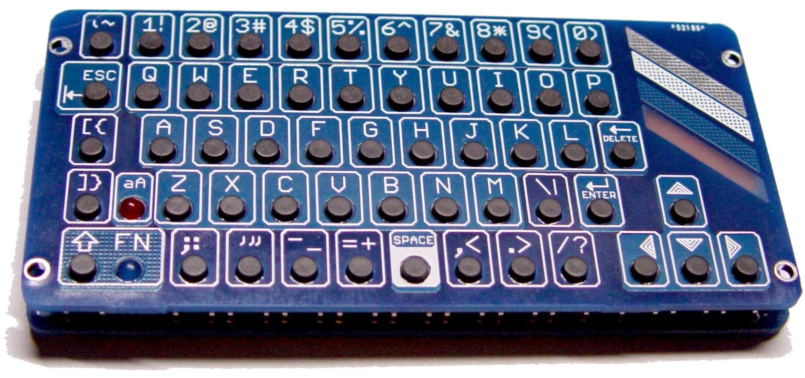
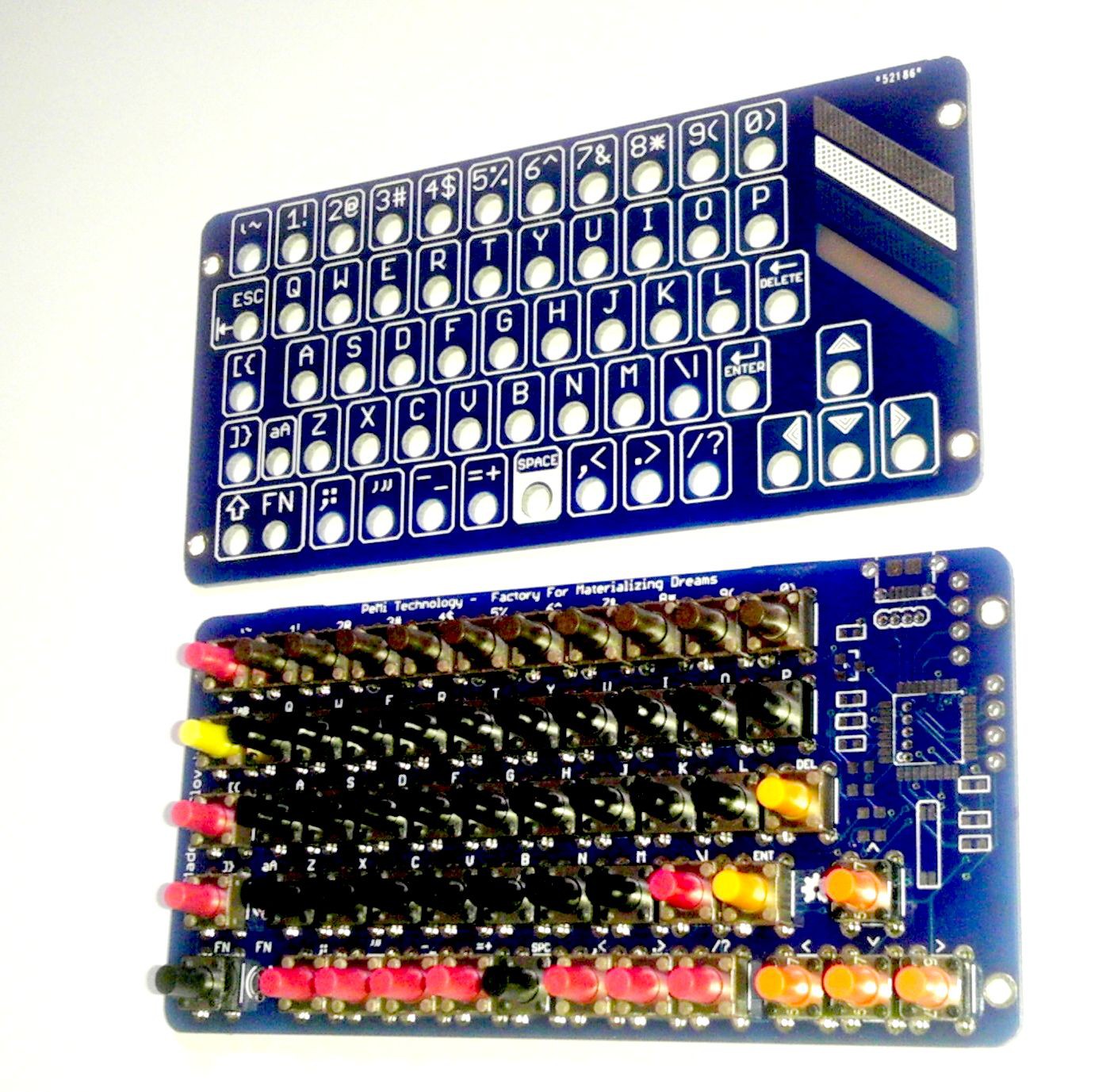
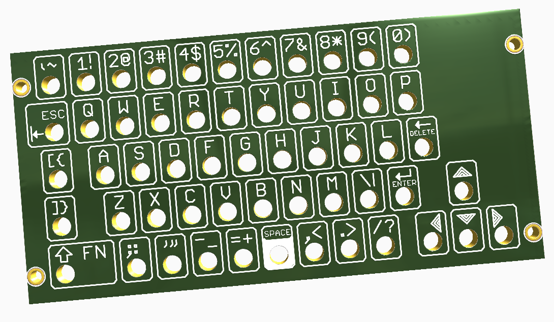
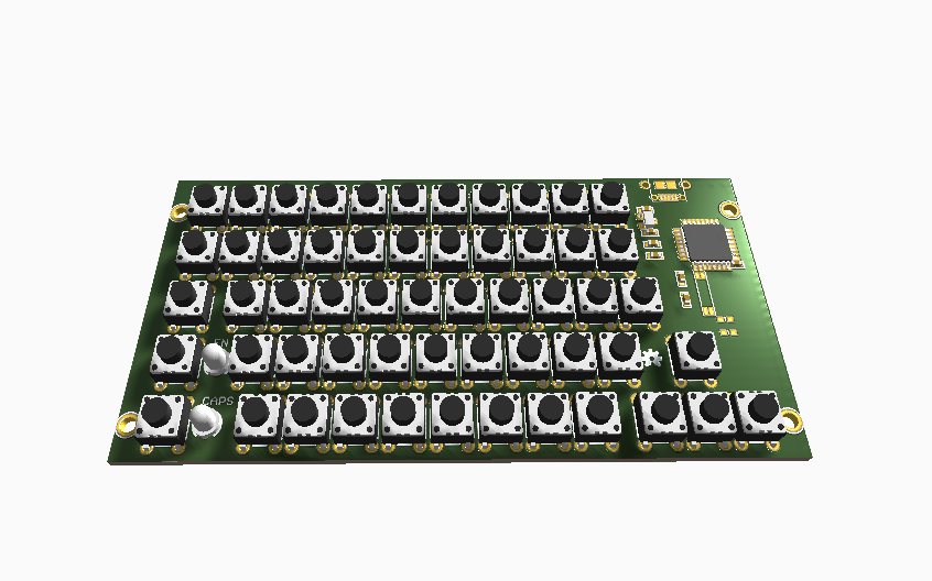
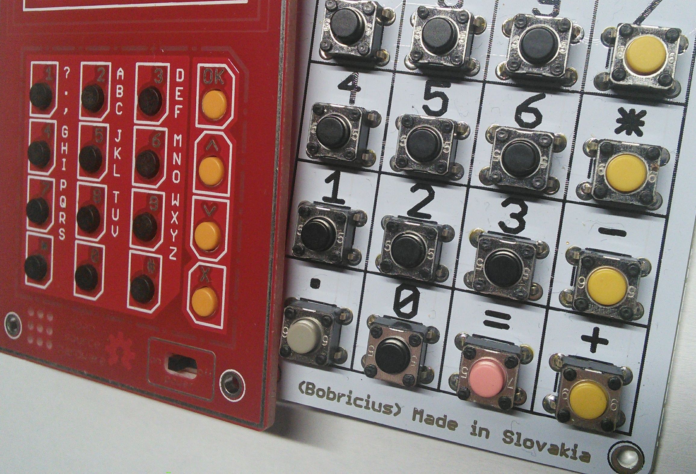
Keyboard is designed as 2 layers
- first top layer - holes and button names
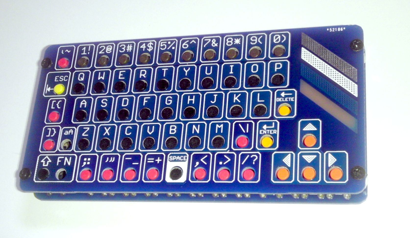
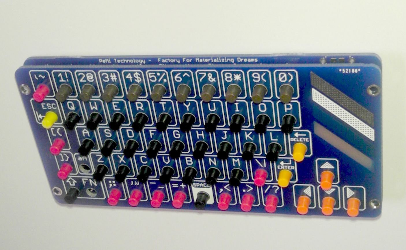
- second layer - buttons and controller
ALL FIT in one 10x10cm PCB ORDER
MICRO CONTROLLER is very powerful is exactly ARDUINO ZERO ...256Kb FLASH you can write
your own keyboard driver in simple arduino IDE
WITH I2C header you can ...
- Add RFID NFC reader
- Add display and get feedback from computer (like terminal)
- add sensors (temp, humidity, pressure, light)
You can also create standalone computer :)


 Awesome Makes
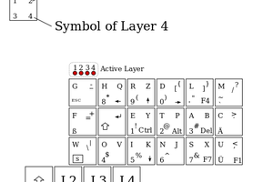
 deʃhipu
Will it work with Monome Norns Shield https://monome.org/docs/norns/shield/ ? It is based on raspberry pi and supports usb keyboard input