0%
0%
Sphere ROV: 8BitRobots
A novel underwater spherical robot powered by the 8BitRobots module
 Tim Wilkinson
Become a Hackaday.io member
Already have an account? Log in.
Just one more thing
To make the experience fit your profile, pick a username and tell us what interests you.
Pick an awesome username
hackaday.io/
Your profile's URL: hackaday.io/username. Max 25 alphanumeric characters.
Pick a few interests
Projects that share your interests
People that share your interests
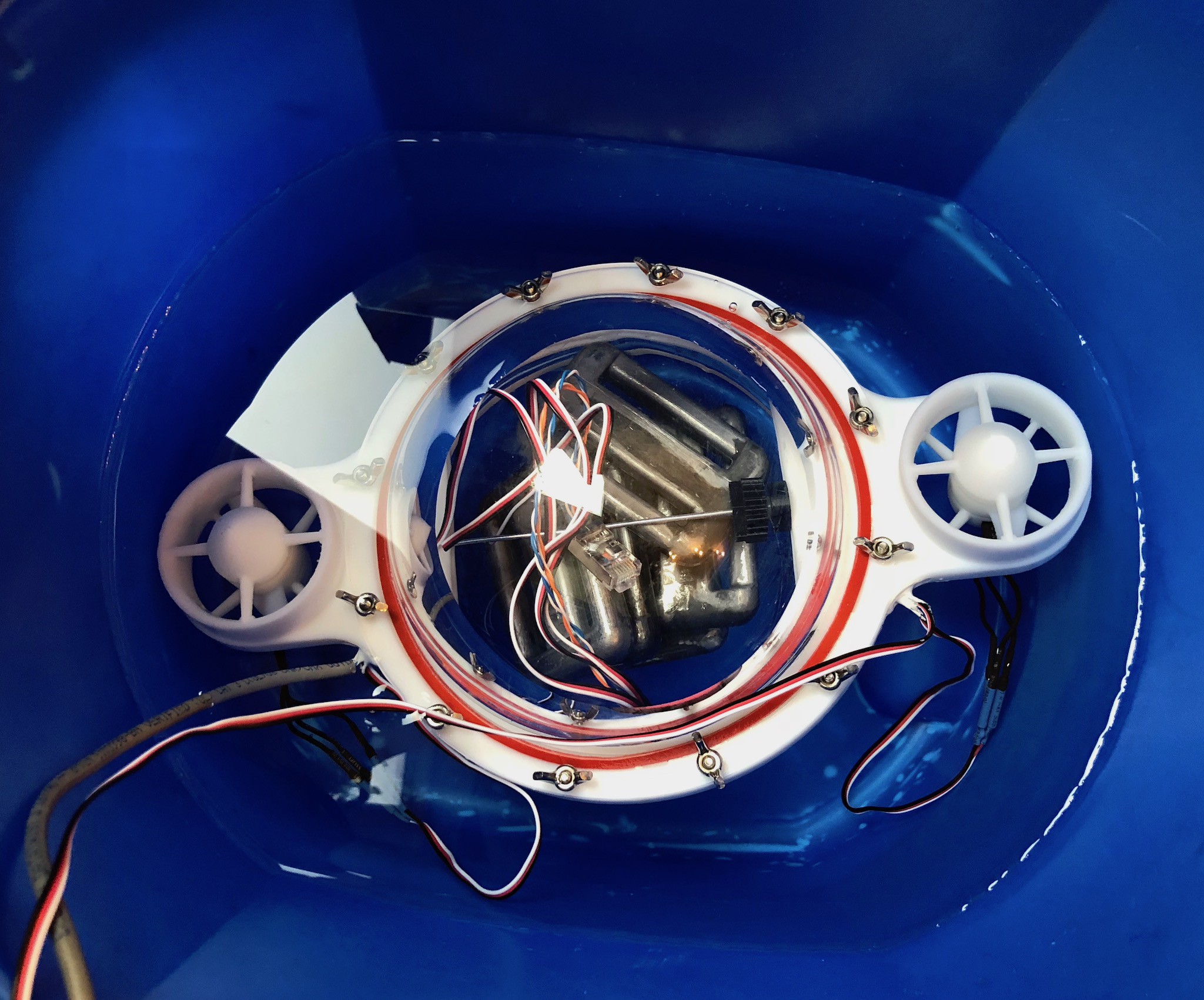
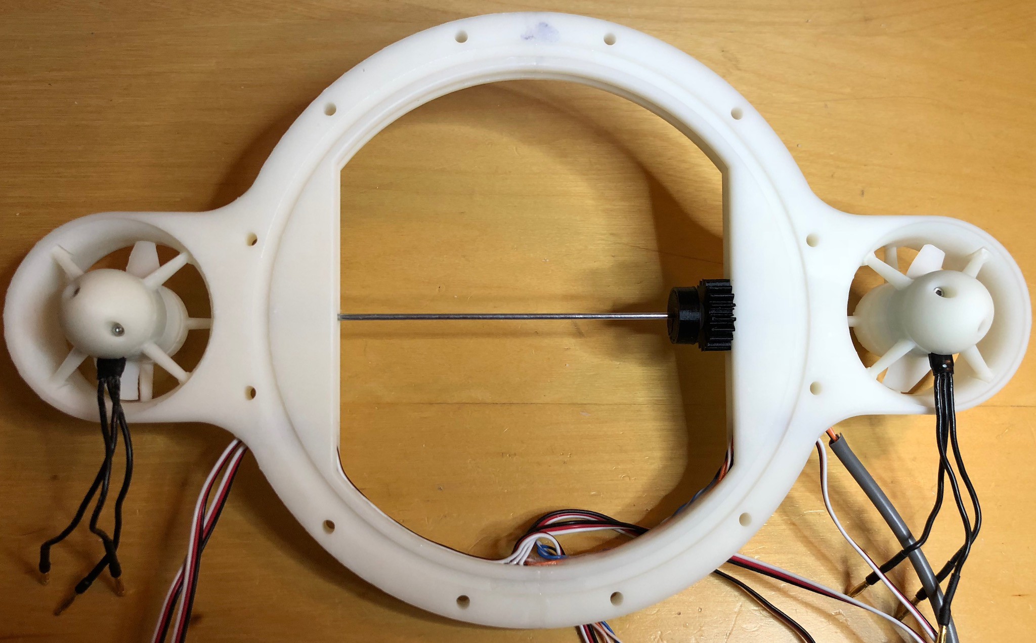
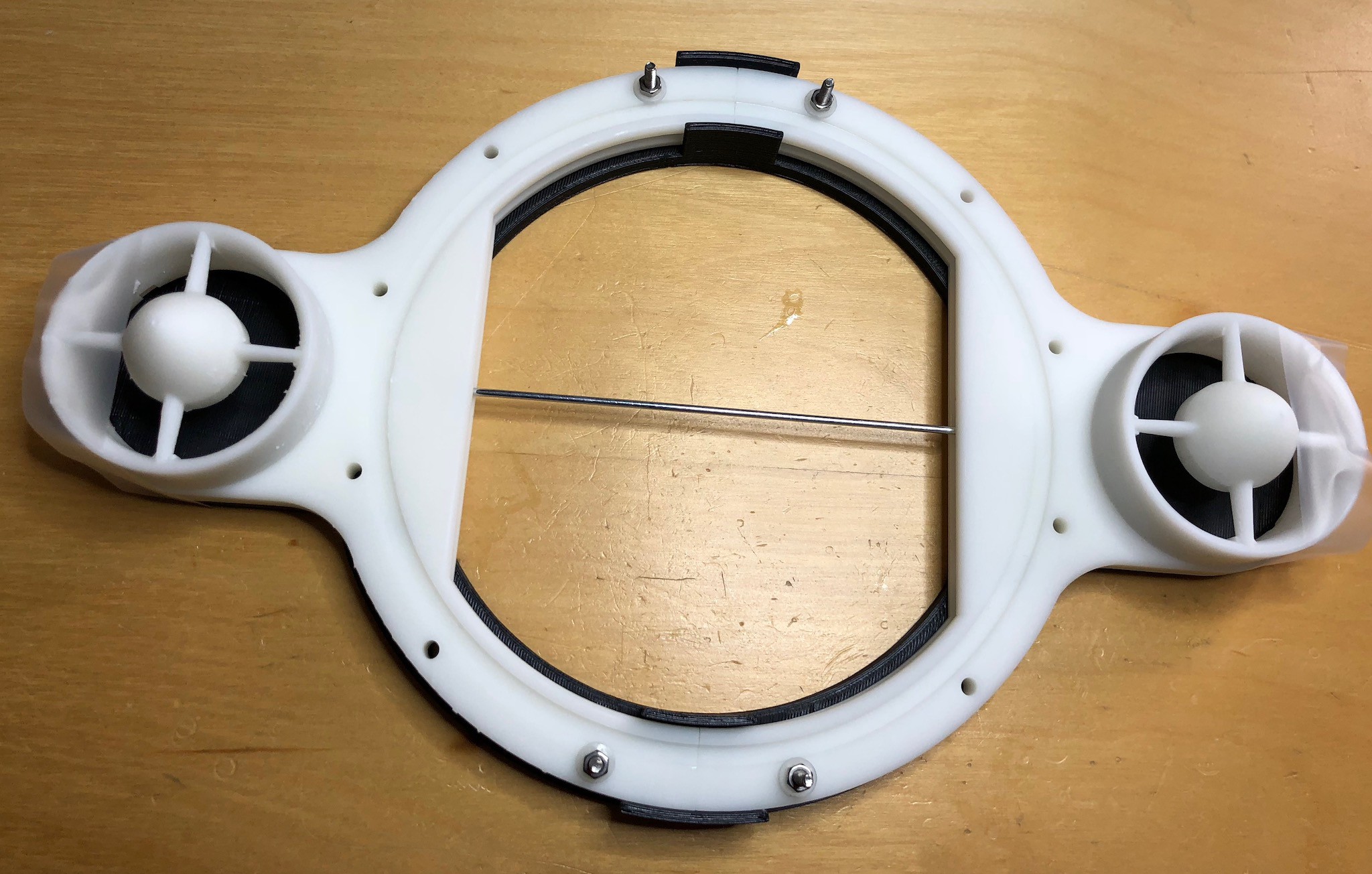
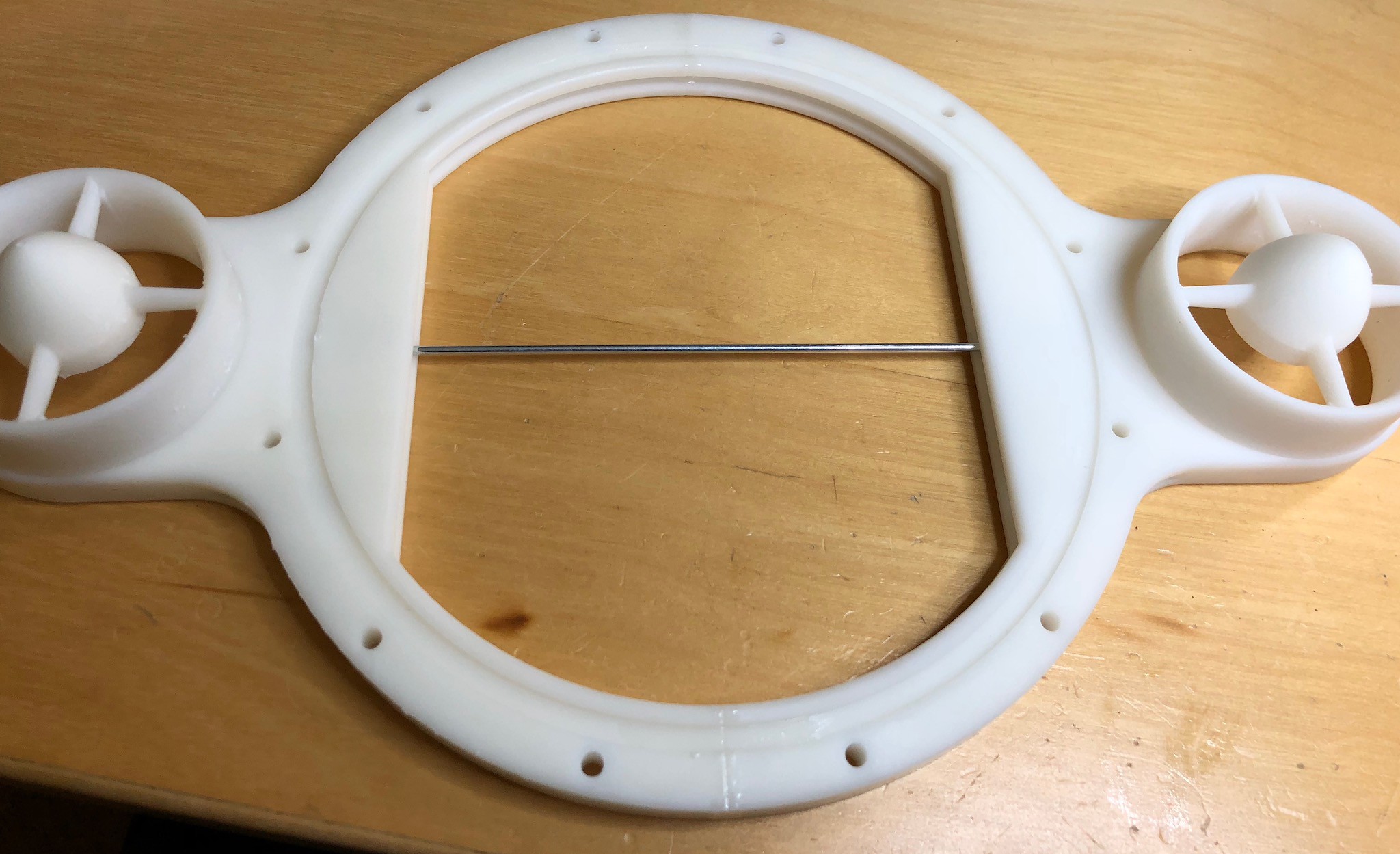
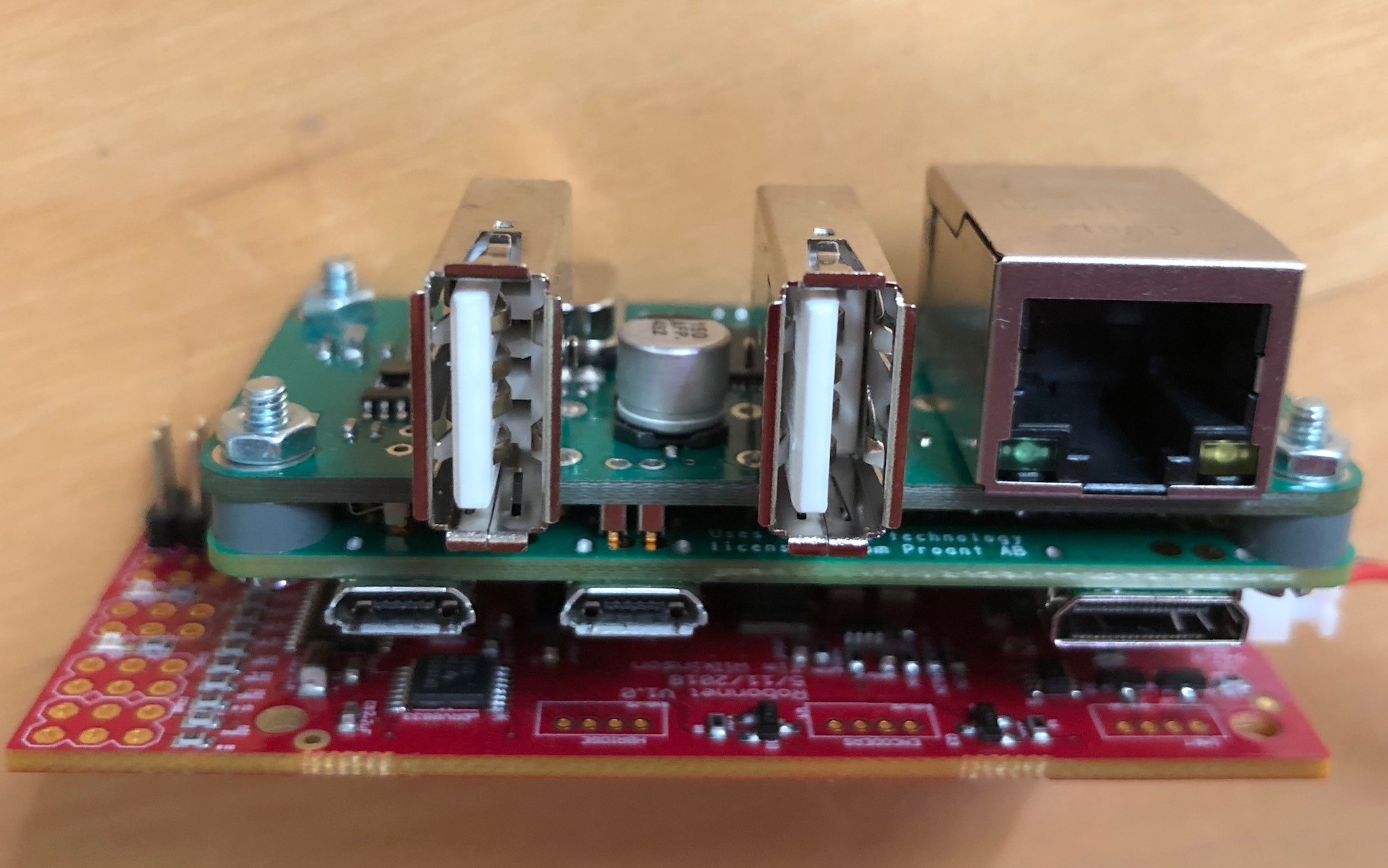
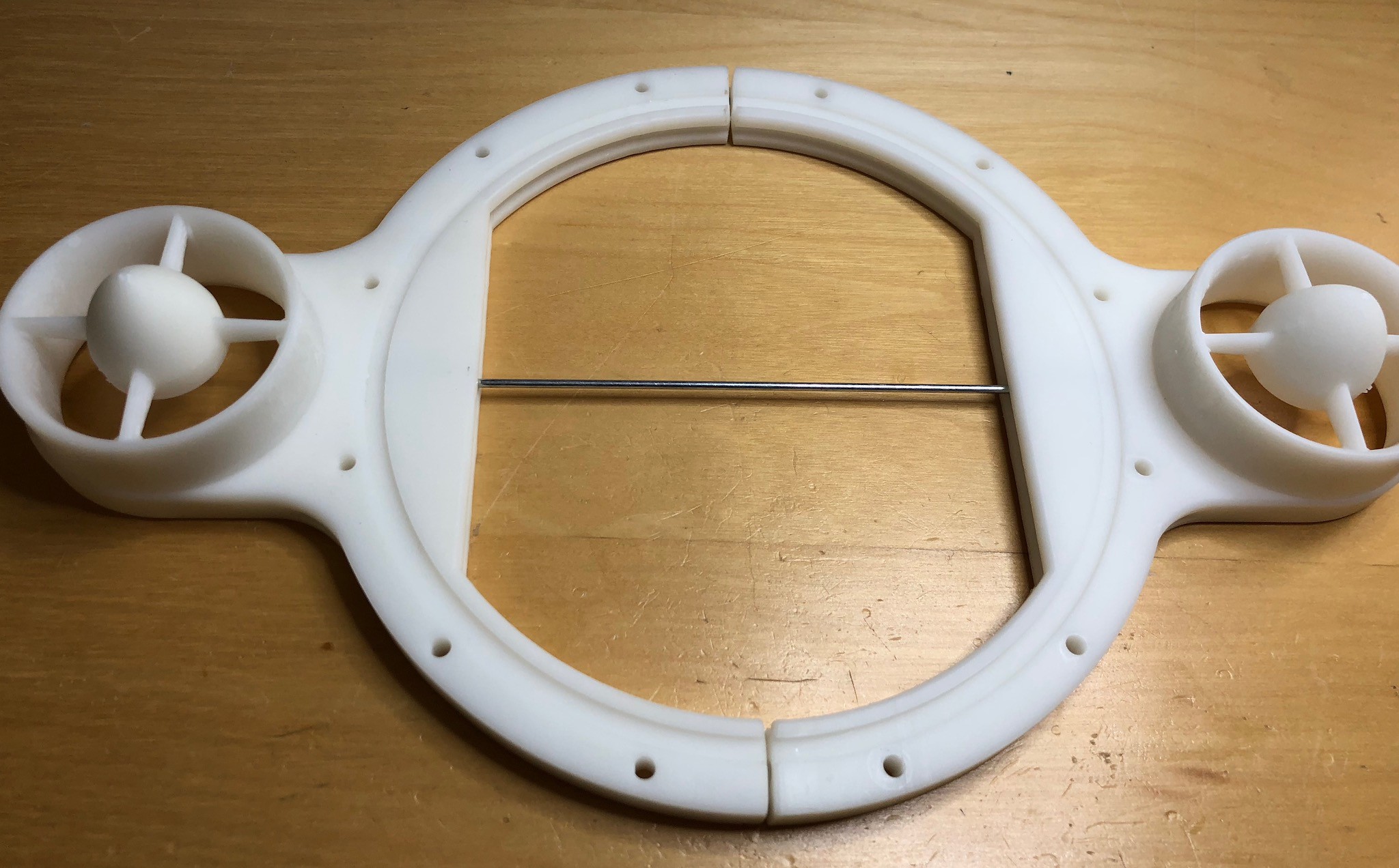
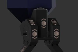
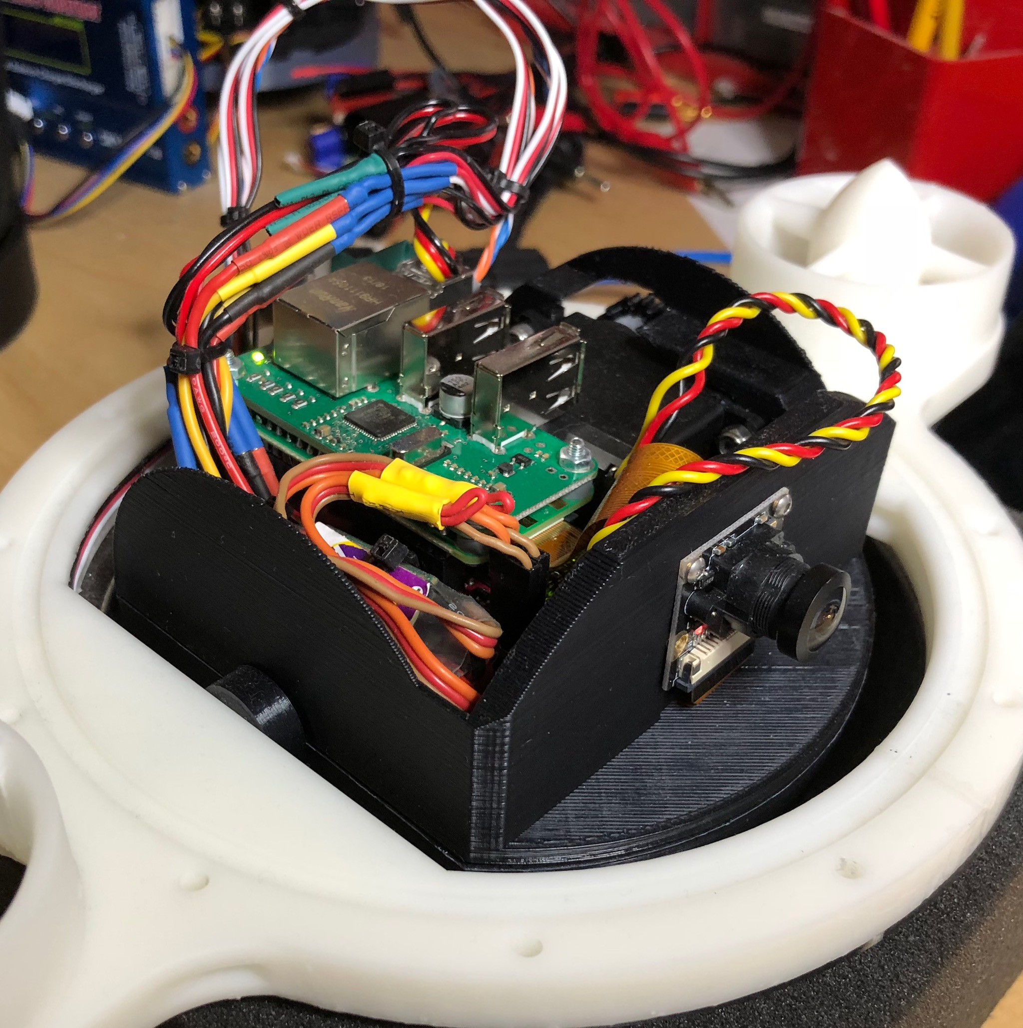 The above photo shows all the ROV internal assembled inside the frame (the photo below shows the same assembly from the back)
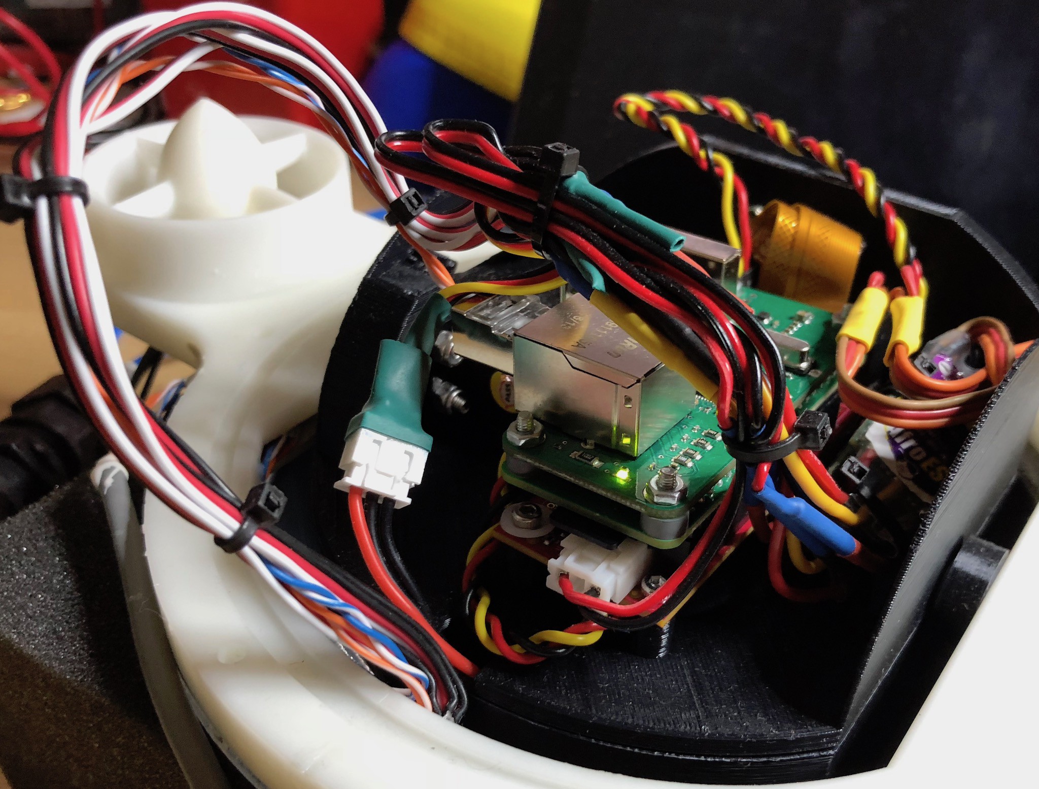

 Morning.Star
 Abhishek
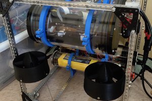
 Joseph Marlin