 Lukas Fässler
Versatile stand-alone or as a Module
While this project started as a stand-alone solar charger, is is nowadays often used as a module in larger projects. The prime example of this is MeshPoint, a WiFi hotspot for disaster and outdoor areas. That project is all about WiFi and 4G mobile networks, not about power harvesting. Using this solar charger as a module, Valent and his team can focus on WiFi connectivity without getting overly distracted with power management.
Don't re-invent the Wheel
Whatever your project, if there's no wall outlet nearby you will sooner or later have to worry about power. Developing a quality solar charger is a major project in its own right as I have found out over the course of the last few years. Chances are high that your project's specific requirements can be met by this charger. It works with many types of batteries over a wide power range. Very often, it is only a matter of configuration to make it fit your needs. So don't re-inventing the wheel. Use this solar charger as a module in your project and focus on what you really want to archieve.
For more involved projects like MeshPoint mentioned above, you may decide to customize the hardware by laying out your own PCB so that it pysically fits and maybe even strips some features that you don't need. Even so, the work involved is only a small fraction compared to starting from scratch.
If your can live with the hardware as it is, your life is even simpler. Just decide if you need the user interface or not and start configuring your charger. The various interfaces from SPI over I2C to USB make it easy for your application to communicate with this charger.
Standalone Use
There are many situations where one needs (or would simply like to have) power but there is no wall outlet anywhere near. Be it a camper van, a boat, or an off-grid hut. Its nice to have some power for electric lighting, charging cell phones and more. And the availability of affordable solar panels makes solar often the energy source of choice in such situations.
Yes, you could just buy one of the countless solar chargers out there. But if you are like me, you want a bit more than a black plastic box. I want to see what's going on, I want to be able to control and configure it, I want to be able to adapt it to my specific needs. I want to be able to connect my laptop computer and see what it did while I was away. If you are so inclined, this charger is for you.
Beyond Energy Harvesting
There are also ways how this charger can support your project beyond providing energy. For example, you can access the real-time clock and calendar via any of the interfaces. You may also store data on its EEPROM or its 4MB flash chip.
If your project is about logging environmental data, you may even rely entirely on this project. The two analog inputs originally intended for temperature measurement can also be used for other purposes. If you need a bit more than that, you can connect an external ADC directly to the I2C or SPI interface and let the solar charger do all the work. All you will need to do is to customize the firmware so that it takes care of your extra hardware.
Beyond Solar
There is even a project harvesting wind energy that decided to use this solar charger as a starting point. While a wind turbine is certainly different from a solar panel, there are many similarities. It's all about extracting as much energy as possible and converting it in an efficient way. Starting with this open source design saved countless hours in both software and hardware development.
Features & Details
High Efficiency DC-DC Buck Converter
At the core of this project is a highly efficient DC-DC switcher rated at 75 watts and entirely controlled by software. It operates at 187.5kHz and can operate both in synchronous or asynchronous mode. The latter is more efficient at light loads. Together with the careful layout and thoughtfully chosen components this allows for an efficiency in the range of 97% from about 1 to 75 watts. That means no heat sinks and no fans which helps keeping size and cost down.
You may connect a 12V solar panel of any size. It's totally ok for the panels to exceed the charger's 75 watt power rating. It is smart enough to not draw more current than it can safely handle. And the MPPT (Maximum Point of Power Tracking) algorithm makes sure that the panel is operated at its most efficient voltage/current combination when power is needed.
Very Low Standby Current
Being efficient when harvesting power is only one side of the coin. In many applications, especially low-powered ones, it is equally or even more important to preserve power when there is no sun. And this is where many other chargers fail. This one uses a very low quiescent current power supply and a low-power microcontroller. When in standby mode, the board voltage is lowered from 3.3 to only 2.2 volts and any unused sub-circuits are entirely powered off. The system clock is also lowered from 48MHz to only 32.768kHz. All that allows power consumption to be lowered to only about 100 microamps while still logging data.
Works with any kind of Battery
Unlike most other solar chargers, this one works with a very wide range of batteries, both big and small. You can use a standard 12V lead acid battery but you don't have to. You may just as well use a 3-cell Lithium Ion battery. Or LiPo. Or NiMH or what ever size and technology fits your project. All parameters such as maximum charging voltage, maximum charging current, minimum discharging voltage and so on can be specified and may even depend on ambient temperature. As long as the battery's nominal voltage is in the range of 6 to 13 volts it fits.
Precision Measurements & Data Logging
A carefully designed circuit and a 16-bit ADC with a precision 2.048V voltage reference is used to measure voltage and current at both input and output. Besides that, the PICs internal 12-bit ADC and a 2.5V reference are used to monitor the on-board voltage as well as up to 2 external temperatures.
All that data as well as information on other system parameters is stored in a log file every 5 minutes. There is enough on-board storage for about a year of data logging. A real-time clock and calendar acts as a time reference and provides a time stamp for every data set.
USB Interface & Bootloader
The charger acts as a composite HID (Human Interface Device) / MSD (Mass Storage Device) when connected to a host via USB. The HID interface connects to the dedicated SolarCharger App which allows the user to monitor and control the charger. The MSD device class allows the firmware to be easily upgraded in the field without the need for a programmer or any host software.
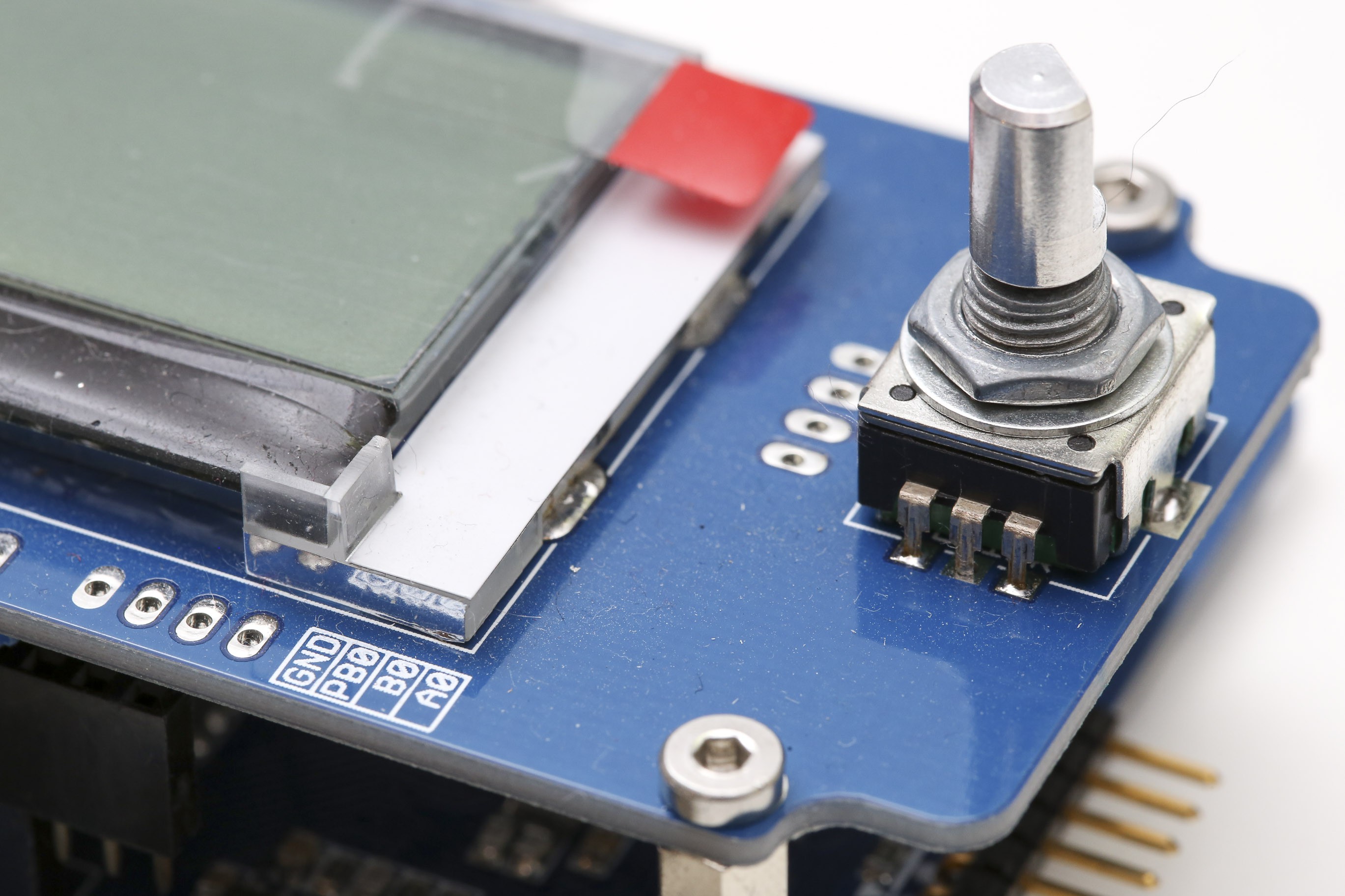
LCD Display and Rotary Encoder
There is a user interface with a high contrast 4 lines times 20 characters LCD and a rotary encoder with push button that lets you monitor and control the device. If your application doesn't need a user interface, just leave it away and use some other interface.
SPI and I2C Interfaces
If you integrate this charger into a bigger project, you may want to use a simpler protocol than USB to communicate to this device. Then all functionality is accessible via I2C or SPI. These interfaces can both operate in both master or slave mode. In future releases of the bootloader it will even be possible to upgrade the firmware through these interfaces.
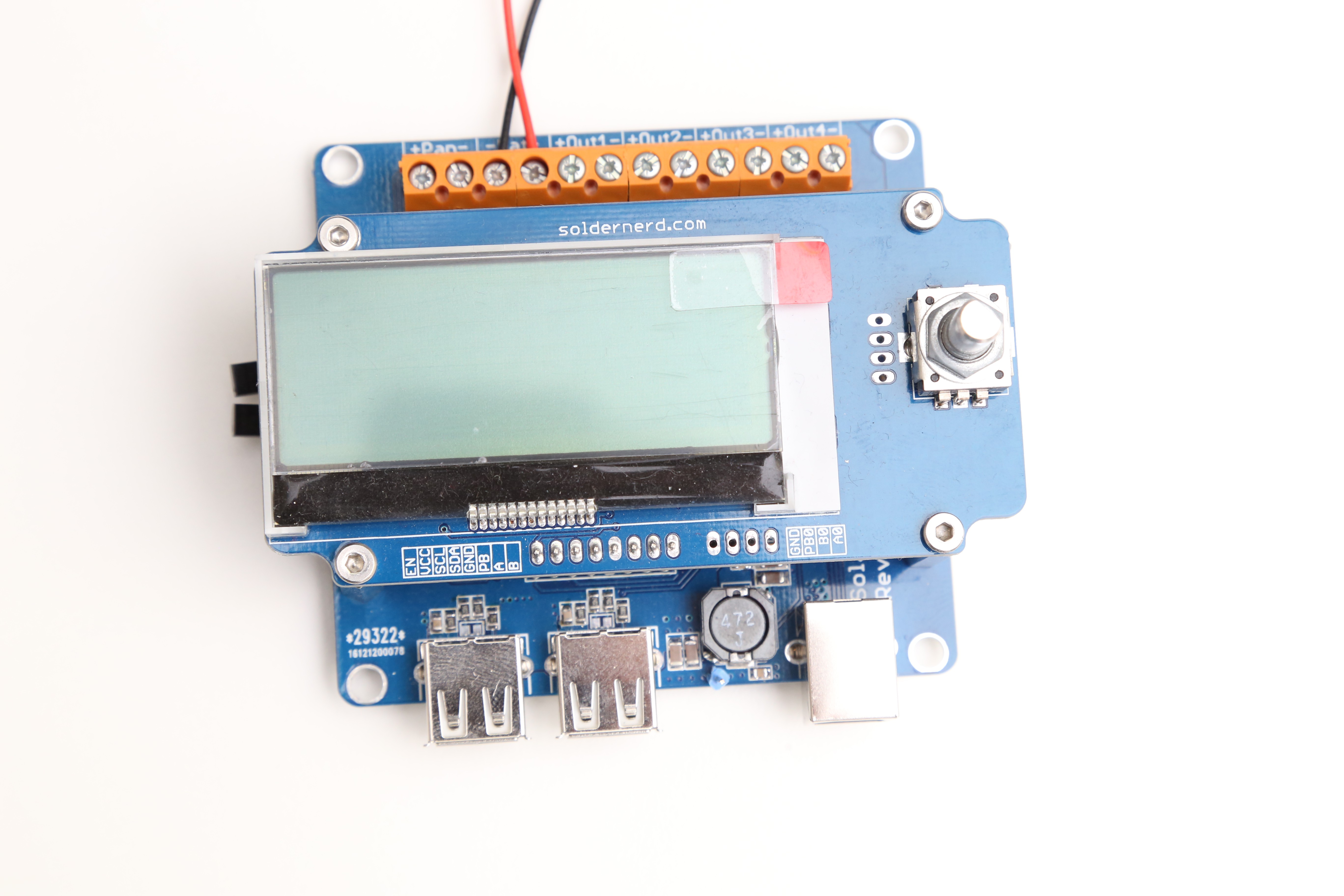
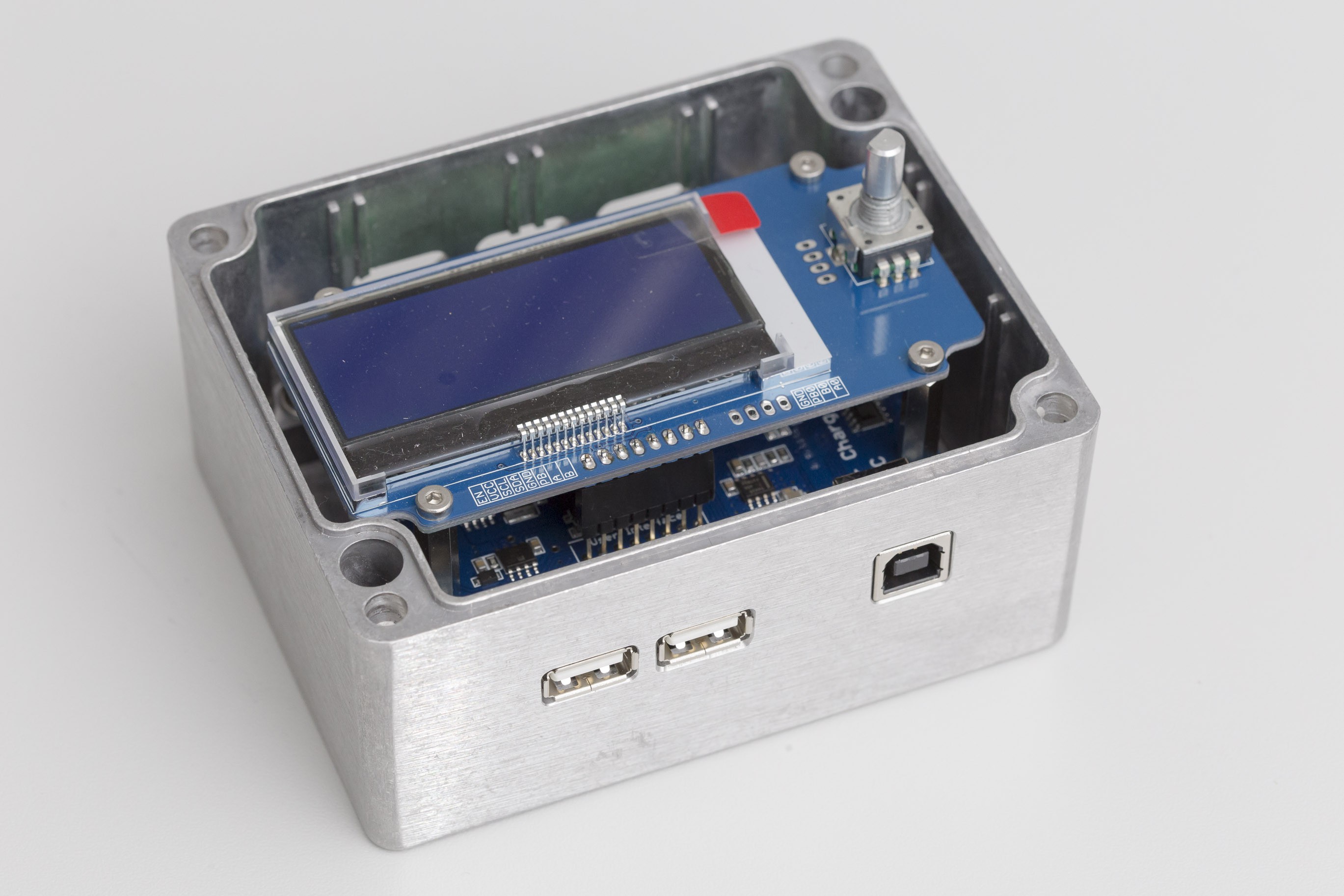
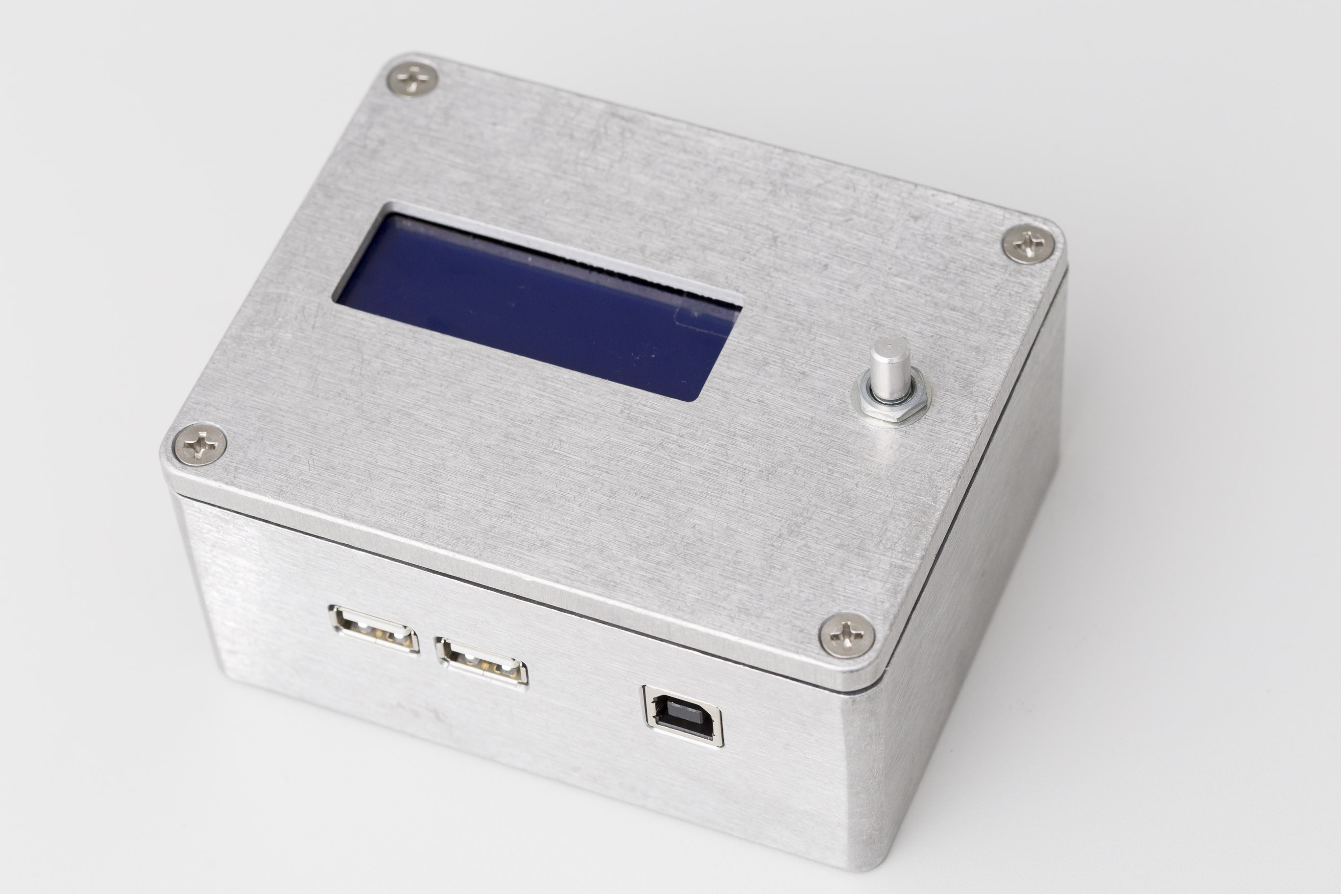
USB Charging Ports
There are 2 USB charging ports with a total of 4 amps of current. That's enough to fast-charge two tablets simultaneously. Compatible with Samsung, Apple and just about any other device.
4 PWM power outputs
There are 4 powerful outputs that can be individually switched on and off or even be PWM controlled. So they are ideal to control LEDs or whatever other gear you may want to power.
Fan output
In most applications, there is no need for a fan. If your project needs one anyway, there is a dedicated output for a temperature controlled fan on the board.
Open Source Licenses
All my work for this project is published under Creative Commons Attribution-ShareAlike 4.0 International(hardware) and GNU GPLv3 (software). So feel free to use and adapt anything you find here on hackaday.io, the linked github repos or my personal blog as long as you give credits to the original authors (attribution) and again share your design (share alike).
All hardware design was exclusively done by me so there are no further restrictions. The same goes for most of the software. However, for the USB implementation I have relied on some application notes and code samples provided by Microchip. By my understanding of their terms of use, one may adapt and re-distribute that code in a way that is compatible with GNU GPLv3 but I'm not an expert on this.
Where to find more information
While this project description itself has already grown considerably, most of the documentation for this project is hosted on my personal blog, soldernerd.com. There, I have documented many intermediate test results as well as the design decisions and tradeoffs that have shaped this project. There is an overview of all posts related to the solar charger project at https://soldernerd.com/mppt-solar-charger/.
The project can be divided into a total of 5 sub-projects, each of which has its own github repository:
Solar Charger Board / Hardware
Mainly the Eagle files and gerbers of the various revisions of the main PCB. Latest version is Rev F.
Progress: completed. Final gerbers and BOM can be found under Files.
Github: https://github.com/soldernerd/SolarChargerHardware
User Interface Board / Hardware
Eagle files and gerbers of the various revisions of the user interface PCB. Latest version is Rev C. This sub-project is extremely universal and not at all specific to the solar charger. It can operate from 3.3 or 5 volts and is a self-contained user interface with a 20x4 character LCD and a rotary encoder with push button. The display (including backlight brightness and reset) are controlled via I2C.
Progress: completed. Final gerbers and BOM can be found under Files.
Github: https://github.com/soldernerd/UserInterface
Solar Charger Software / Firmware
This is the most work-intensive part of this project. All the software that runs on the PIC18F47J53. It is written in C using the (free) Microchip MPLAB X IDE and the free version of the Microchip XC8 compiler. Board revisions prior to Rev E used a different microcontroller and hence require slightly different code. That code is also on github (in a different repository) but is no longer actively maintained.
Progress: 80% complete. It's usable and stable but some features such as data logging need more work. Also, much more can be done to reduce standby power consumption. This is currently the focus of my work.
Github: https://github.com/soldernerd/SolarChargerRevE_Software
USB Bootloader
This essential sub-project enables the non-technical end user to easily and reliably update the firmware in the field. It is written in C using the (free) Microchip MPLAB X IDE and the free version of the Microchip XC8 compiler. Unlike the firmware, this code is rather universal and can be used for other projects using a PIC18 with relatively few modifications required.
Progress: 95% completed. I've worked very intensively on this code over the last two months and it's now pretty complete. It's much faster now than it used to be and comes with a feature-rich API that is available via USB HID or SPI. The only thing left to do is to make the API available via I2C as well.
Github: https://github.com/soldernerd/PIC18_USB_Bootloader
Solar Charger App
A windows WPF application wirtten in C# to communicate with the Solar Charger over USB. One can monitor and control the charger via this program, look at the logged data and set the calibration parameters for the various measurements.
Progress: 95% completed. Works well and reliably but will likely see a change here and there.
Github: https://github.com/soldernerd/SolarChargerApp
Brief Project History
This project started in 2015 as a simple Arduino Uno solar charger shield intended to provide power at a friend's allotment garden. The device performed remarkably well but the Arduino's inherent limitations became obvious. First of all, it consumed way too much power and limited the switching frequency to 62.5 kHz which meant that a bulky inductor and large power capacitors were needed.
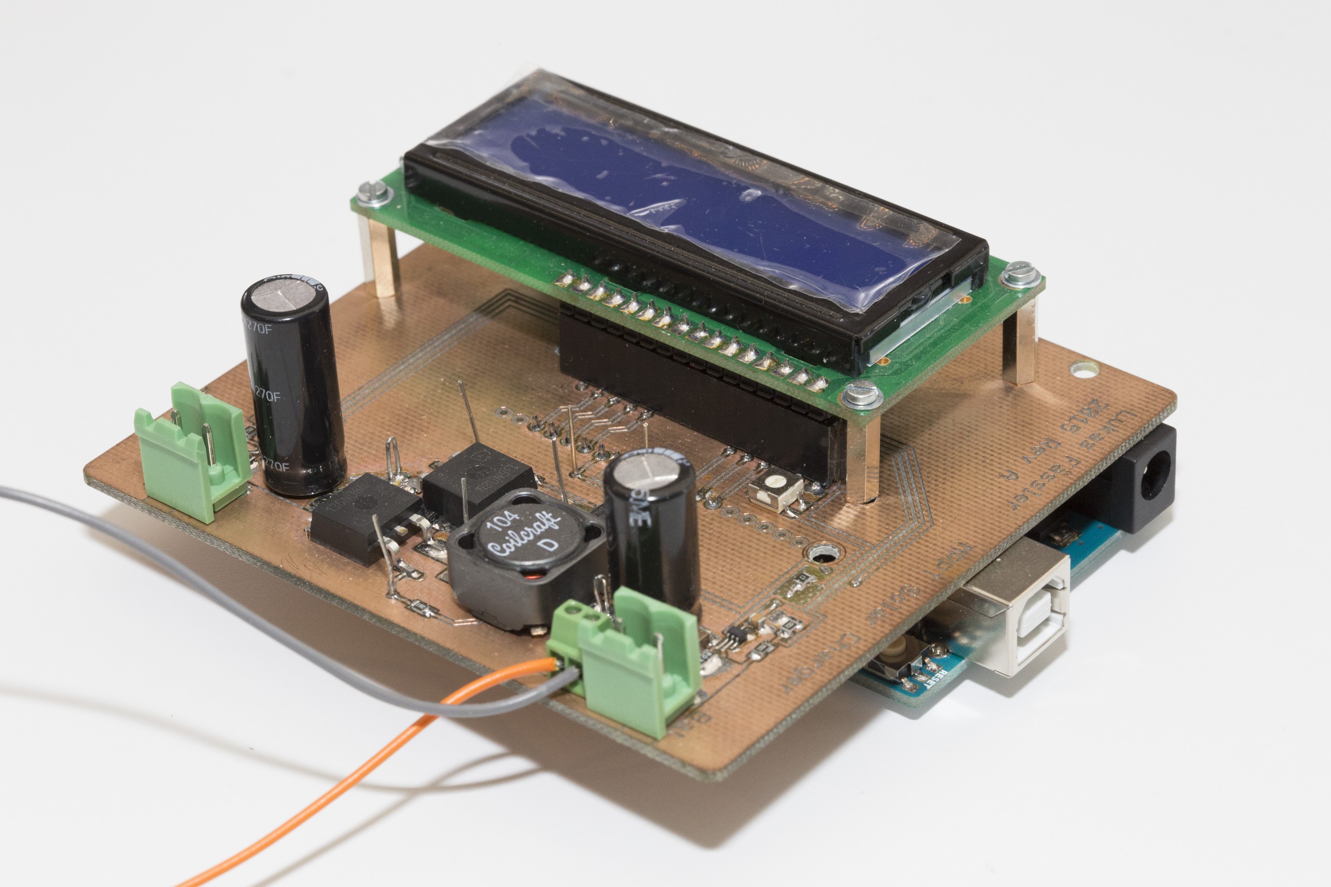
So I designed a much more ambitious charger based on a PIC18. While it was physically larger and built on a home-made board, a lot of the features and solutions can still be found in the latest revision. It was designed with low power consumption at its core. While it came with lots of new features like USB interface, USB charging, switchable power outputs and so on, all those features could be turned off when not in use. Revision A was born.
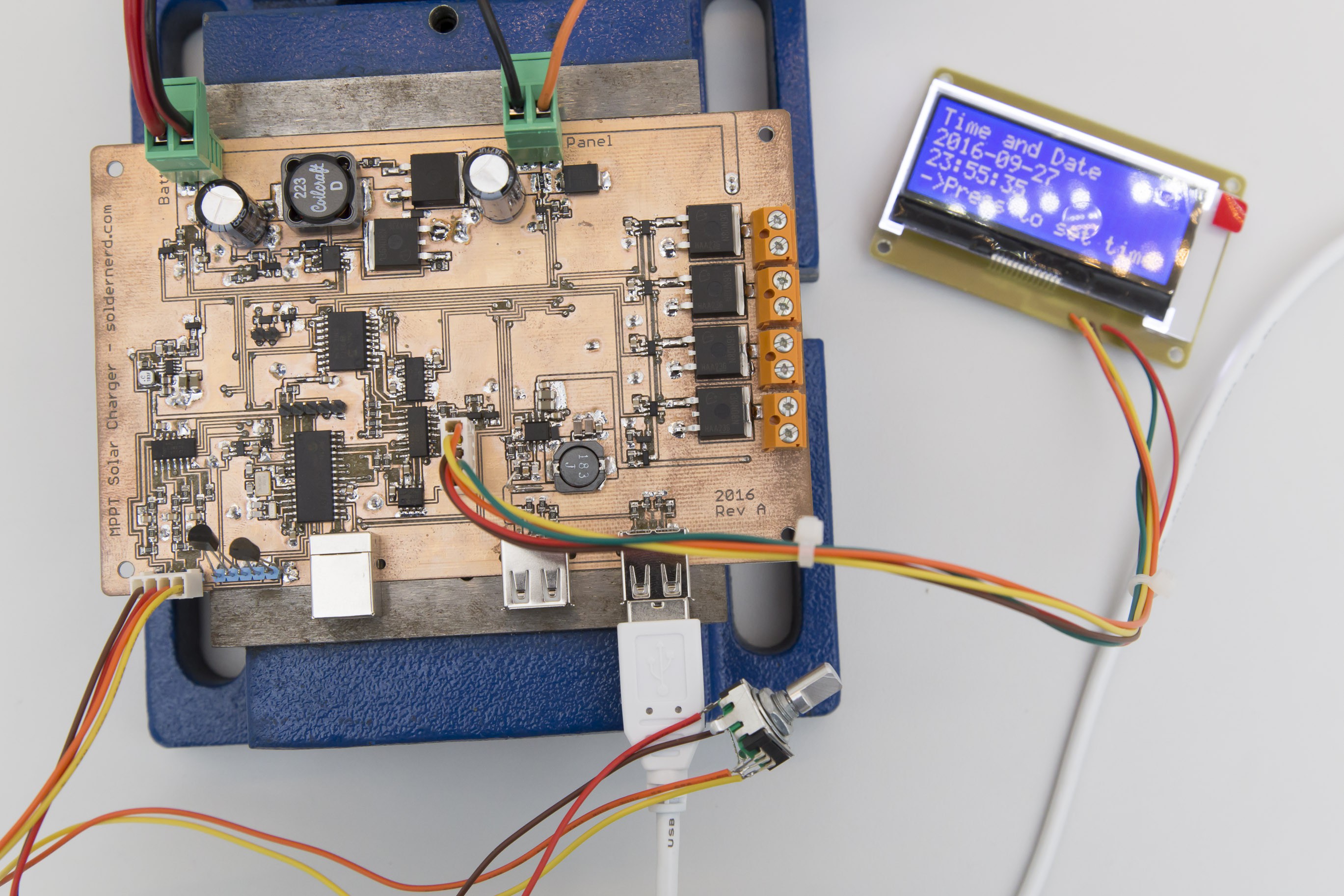
When programming and testing the new version, some design flaws became aparent but the general concept seemed to work so I went to work on the next version. Besides fixing some issues I had with Rev A, the whole design was streamlined and reduced in size. Both component costs as well as the number of different components were significantly reduced. I also decided to move the user interface consisting of a 20x4 character LCD and a rotary encoder with push button to a separate board - something that hasn't changed since.
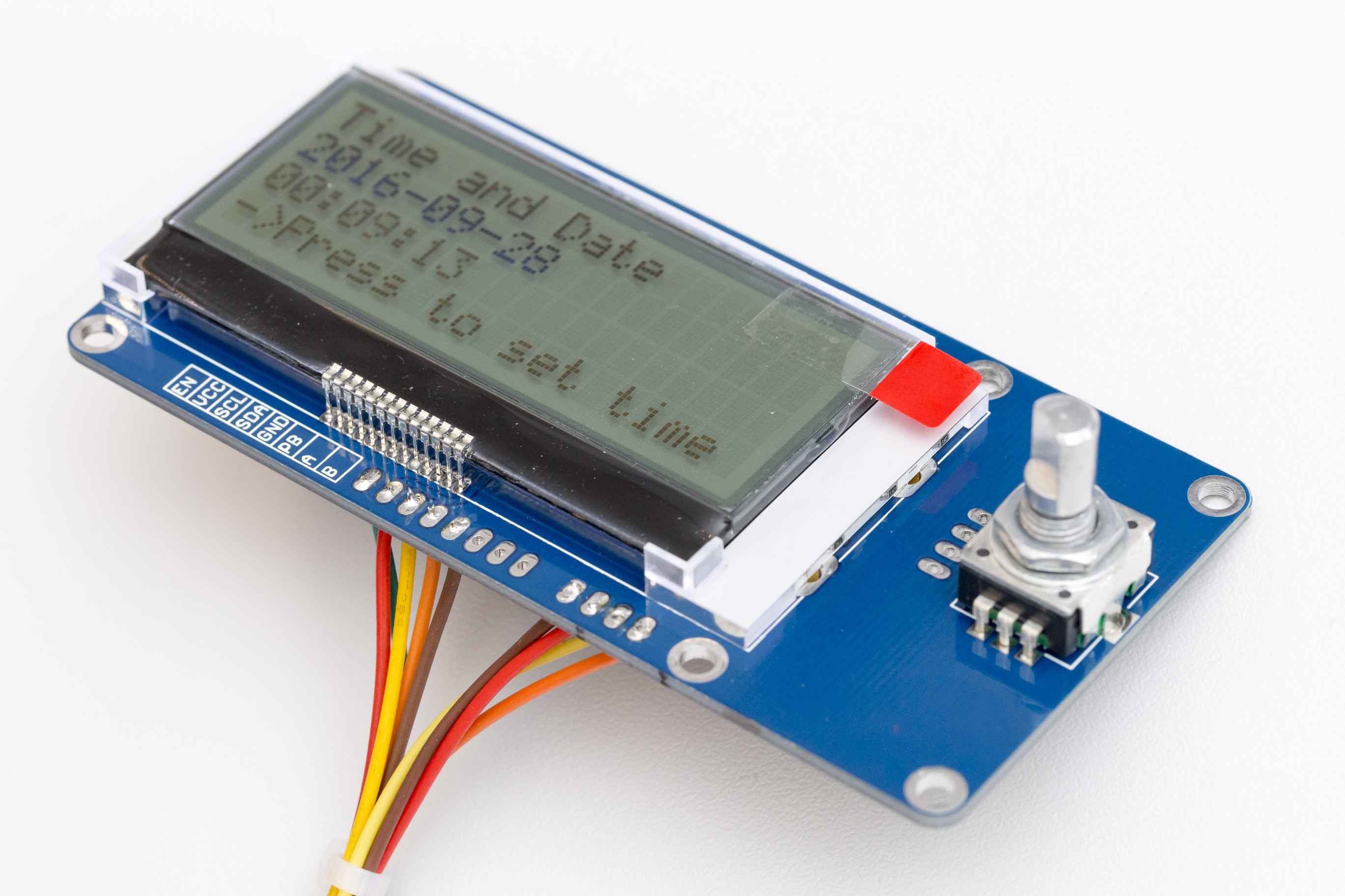
The user interface can be disabled and put into a very low power state. But even when disabled, it has the capability to wake up the charger when the push button is pressed. All the signals from the rotary encoder are debounced in hardware right on the user interface board. Also important, when disabled, the A and B outputs (as well as the I2C signals) assume a high-impedance state and so don't interfere with the PGD and PGC in-circuit serial programming pins of the PIC that are shared with the encoder. The display is controlled via I2C, including backlight brightness and reset. Like the charger itself, the display has gone through a few revisions but the general design has remained unchanged.
While in this project, the user interface operates on 3.3 volts, the very same board can also be used in 5V projects by just changing a few resistors. This makes this user interface very universal. One can use it in just about any microcontroller project that needs a user interface and has an I2C bus and a few spare pins.
The new, professionally etched boards (starting from Rev B) made prototyping much faster and more reliable. Also, they were layed out with a (generic) enclosure in mind. As mentioned before, the board has gone through a number of revisions but changes have really become minor in later revisions. I'm happy to say that the latest version, Rev F, can be considered a rather mature design that is unlikely to see any significant changes.
If you would like to read more on how this project has evolved, you are invited to read the entire series of posts on my blog, soldernerd.com. There, I tried to document not only the results but also the thoughts and design trade-offs that have shaped this project.
For all the code and eagle files you are referred to github.com/soldernerd where there are separate repositories for the main board, the user interface, embedded software, host software as well as the boot loader.