Close
0%
0%

French Nixie Clock

My take at making a Nixie Tube clock, with basic time keeping through an RTC chip, as well as more advanced functionalities.

Similar projects worth following
I will walk you through all the stages of the development of a Nixie clock, from early design stage and concept, to part-picking, 3D modelling, PCB design, coding and finally assembling and getting a functional, long lasting, stylish product.

This is an on-going project updated live, so it will take a while to finish it, and I will consider any ideas or suggestions you may have. Feel free to comment or contact me for information.

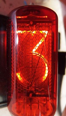
A year ago I discovered Nixie tubes. Little light bulbs you're most probably already familiar with, but I was fascinated by this old technology built to last. Though today, Nixie tubes are obsolete compared to newer technology for digits display, their fascinating glow and design is something unlike anything else.

I acquired old French nixie tubes (F9057) on eBay recently, and these would be perfect in a small discreet, and stylish clock. These tubes having been made in the 70's and still working today is incredible. Therefore I would like my design to also last long and I will share with you on a later post how I am planning to do so.

I want the interface to be as simple and straight forward as possible, though still packing a whole lot of technology inside to make an accurate, modern and connected, maintenance free clock.


Main functionalities and design criteria are for now :

  • Precise time keeping
  • Update time through internet connexion or Atomic sensor
  • Possibility to manually set/adjust the time if no internet/signal available
  • Auto brightness/dim to accommodate for day/night display

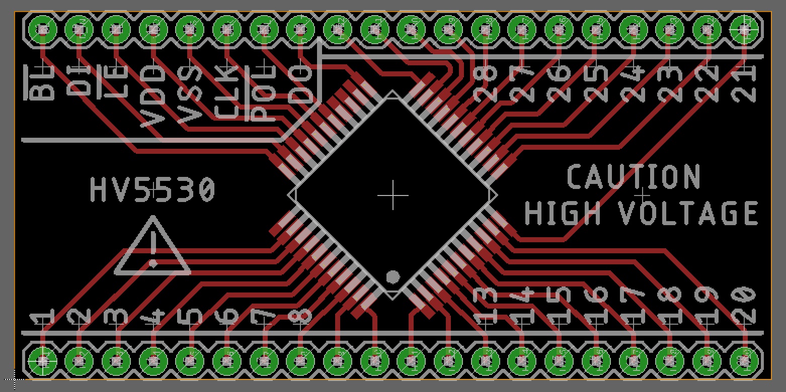
Currently I'm thinking of using the new ESP32 chip for wifi connectivity, an RTC (DS3231) chip for time keeping, a high voltage driver for the nixies tubes (HV5530), and code on Atom Platform IO using the Arduino framework.

I'm will make the various circuits on Eagle, design the enclosure in Fusion 360 for 3D printing, and make some of the enclosure in wood for a stylish finish.


Well, this is the general idea. Anything mentioned above might change as the project gets going, and time will tell if the finished product will look anything like the description above.

HV5530 Breakout Board and Library.zip

HV5530 Breakout Board Eagle Schematic and Board. Contains HV5530 Eagle Library.

Zip Archive - 26.54 kB - 06/20/2018 at 09:34

Download

F9057-Datasheet.pdf

Datasheet of F9057 Nixie tubes.

Adobe Portable Document Format - 404.45 kB - 06/08/2018 at 15:49

Preview
Download

F9057.jpg

Tubes I'm planning to use.

JPEG Image - 175.58 kB - 06/08/2018 at 15:49

Preview
Download

  • 4 × F9057 Nixie French Nixie tubes, though quite difficult to find they have a great finish, and lovely font.

  • HV5530 Driver

    Frederic L06/20/2018 at 09:31 0 comments

    Nixie driving is quite straight forward. Connect the anode to high DC voltage (170-250V according to corresponding datasheet), and ground the cathode of the digit you want to illuminate, leave the other cathodes floating.

    There are a few drivers available, and other projects may use different chips and methods, but I like the HV5530 Shift Register. It handles up to 300V, is 32bits (ie. it can drive 32 cathodes independently), has a Latch (ie. is not constantly cycling through each output, but keeps a steady array of output once latched) and interfaces easily with Arduinos via SPI.

    Vlock Diagram of HV5530
    Extract from the datasheet

    Ideally interfacing is made through 12V (cf. datasheet recommended operating conditions), but from experience it understands 5V inputs without problems. The ESP32 being 3.3V only, may have some communication problem and I may have to use a voltage translator in order to step up my data from the controller to the driver, from 3.3V to 12V.


    The HV5530 doesn’t come in a DIP package and is therefore not breadboard friendly for development and prototyping. In order to perform some tests and make sure it suits the clock needs, I made a breakout board on Eagle and had it manufactured in China.

    HV5530 Breakout Board
    HV5530 Breakout Board

    As you can see below, I made an error in the package dimensions, and had to bend the legs of the chip in order to solder it to the board. You can admire my poor SMD soldering skills here as well (first SMD soldering experience).

    Bent legs due error in PCB package dimensions
    Bent legs due error in PCB package dimensions

    It’s ugly but it works...

    The Breakout board schematic and (corrected) board design with the HV5530 Eagle library are available on this project's files.


    Soon we'll have a look at the driver in action and some corresponding coding examples.

  • Nixie Driving Requirements

    Frederic L06/13/2018 at 13:01 0 comments

    I’m planning to use 4 Nixies for this clock build. A 6 tubes build, besides showing the seconds, only offers the advantage of displaying the complete date in one go (DD-MM-YY or MM-DD-YY).

    The latter can be accomplished if we split the date display in two (DD-MM then YYYY).


    So how, many digits do I need to drive ?

    Well, if we want to have all the digits available to us, this means 4 tubes times 10 digits equals 40 independent digits. Now for a specific clock build, the actual need is lower :

    If we name each Nixie tube of the clock N1, N2, N3 and N4, then :

    For a HH:MM time format, HH will be maximum 23, and MM 59, so for each Nixie :

    • N1 can only be 0, 1, or 2 (total of 3 digits, for 24hrs display)
    • N2 can be any digits from 0 to 9 (10 digits)
    • N3 can only be digits from 0 to 5 ( 6 digits)
    • N4 can be any digits from 0 to 9 (10 digits)

    That lowers our need to 29 digits to be driven for the time display only.

    For a DD-MM date format display DD will be maximum 31 and MM 12 :

    • N1 needs to be able to display digit 3 as well as digits 0, 1, 2 mentioned above.

    A MM-DD date format is already covered by previous digits selection.

    So far we have :

    • N1 = [0 - 3]
    • N2 = [0 - 9]
    • N3 = [0 - 5]
    • N4 = [0 - 9]

    For a total of 30 independent digits.

    This allows to also cover a YYYY year display, with the following limitation :

    We can display all years until 2059 then N3 is limiting the decades value to show. Ideally if we want to display year xx99, then N3 should contains all digits from 0 to 9 but this would bring our total digits required to 34.

    Unfortunately the driver I’m planning to use only drives a maximum of 32 outputs (32 bits), therefore if we have N3 connected to digits 6 and 7 then we have a total of 32 digits driven and covers the years display up to 2079.

    This is good enough for me, and I’d be quite happy if the clock lasts until then. After this date, in theory all would still function except the year display, which would only be available again in year 2100+. After all is this really important ?


    One drawback of this is that some cathodes will never be lit as they are not connected. Those cathodes will be subject to cathode poisoning and may deteriorate over time.

    Example of cathode poisoning, notice the darker/extinguished areas.

    To prevent this, if all cathodes were connected, one can code a cathode preservation routine, which would switch on all digits one after another in order to keep the wear of the whole tube equal and prevent unused cathodes to become contaminated.

    In my case, the only way to prevent cathode poisoning would be to manually swap the tubes 2 by 2 every now and then (not sure about the frequency, but every year should do I guess). Tubes should therefore be connected to the PCB through pin sockets in order to be easily removed.

  • Getting acquainted with F9057 Nixies

    Frederic L06/08/2018 at 16:25 0 comments

    A Nixie tube is in my opinion, a piece of art itself. The way it's manufactured and the way it looks even extinguished is a legacy of what technology was like in the 70's and underlines decades of technological improvements that brought us to where we stand today.

    And the glowing. This orange captivating glow. Something I knew I had to have/make once I got introduced with Nixies.


    Surprisingly, Nixies were not really made to look good, but to be functional. The most common Nixies we find nowadays are the soviet IN-12 ones. They are solid, cheap, and easy to source, but they have one flaw. The '5'.

    The Russians got cheap and decided it was easier to use an upside-down '2' cathode to make a '5'. Though functional, this would have been better if they had designed the 2 with more vertical symmetry in the first place.

    IN-12 Nixie display font
    IN-12 Nixie character, 2 and 5 are the same.


    For a clock that will throw glowing number at my face all day, I wanted a more harmonious font. And upon searching a bit, I found on eBay some old French F9057 at a reasonable price. The datasheet is available online (in french) and you can find it in this project's files.

    I bought those about 8 months ago, and left them in a drawer until I recently decided to have a go at this project. I bought a Nixie power supply able to deliver 180V DC from a 12V adapter, looked for a breadboard and plugged it in. Here is what the tubes and digits look like.

    Quick tube test
    Quick test on breadboard, 180V DC, anode in series with a total of 52 kOhm resistor.
    F9057 Character font
    F9057 Character font, better than IN-12 in my opinion.

    What do you think ?

    Now that we have the face of the clock, we'll talk a bit about it's heart and how I'm planning to make it tick. Stay tuned.

View all 3 project logs

Enjoy this project?

Share

Discussions

Similar Projects

Does this project spark your interest?

Become a member to follow this project and never miss any updates