INTRODUCTION
I need quite a few solar panel sun trackers to generate as much power as possible from 60 solar panels.
Why? well, we bought a farm in Spain, 120 acres of olive tree garnished paradise.
I'm building a large, off-grid property to replace a derelict farmhouse which is in the mountains of Aragon ...sounds like somewhere out of Lord of The Rings and if I look carefully, I'm sure that I can see Mount Doom somewhere in the Maztrazgo mountains...
Of course, I'm going to need power, lots of it.
I searched the market for a cheap solar tracking unit as my tests in Spain over the last year led me to realise that I need to optimise the amount of power available, especially in the winter. A tracking system will optimise the sun power that I can use and extend the times of day when maximum power is available.
In the area of Matarranya where I'm building (see www.offgrid.casa), there are a number of other off-gridders dotted around, however, they generally use gas or oil for heating and cooking plus around a dozen solar panels for basic electrical requirements. They end up running their generators for much of the winter and that goes against my principle of no carbon based fuel brought to the land. Carbon-based wine is a different matter, however. That is allowed by the truck load.
My guiding light is that I want my house to be really, properly and totally self sufficient - i.e. all electric, powered by a combination of solar and some wind. Basically, I want to be different. Also, I don't want to have to haul off into town which is 10 miles away down a dirt track just because I run out of cooking or heating gas.
In the summer, folk just put up with the heat as they generally don't have enough power for aircon. However, I'm going to use reversible air source heat pumps with under floor piping to heat the house in winter and cool it in summer. This means that the concrete floors become a thermal battery and I can either put heat into the floors ar remove it during the day when power is plentiful and cut it off at night to avoid battery drain. A huge hot water tank also run off a separate air source heat pump will be another thermal battery - additionally, a pair of immersion heaters will allow me to heat the water to around 85 degrees celcius (185 fahrenheit) whenever there's spare power. I'll also automatically switch on the charging power to my Tesla if there's any power left over - see, I don't even need fuel for the car...admit it, you were wondering if I was actually a hypocrite with a planet destroying gas guzzler. My son calls it "electric smugness" and, apparently, I have it in spades. Can't see it myself though.
Tests have been done with a neighbour who has now finished his house. Last winter he kept his house at a steady 22 degrees celcius (72F) and ran his electrics all winter from 15 x 260W panels. Obviously, 6 inches of insulation in the walls and floors helps. However, once the house has attained the correct temperature, it doesn't need much input.
SOLAR TRACKING
My early trials just used a single axis tracking system. The first video shows the first tests in my workshop. There's also a bit of a tour of the 8-channel solar power monitor and mains inverter interface if you're interested.
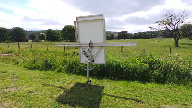
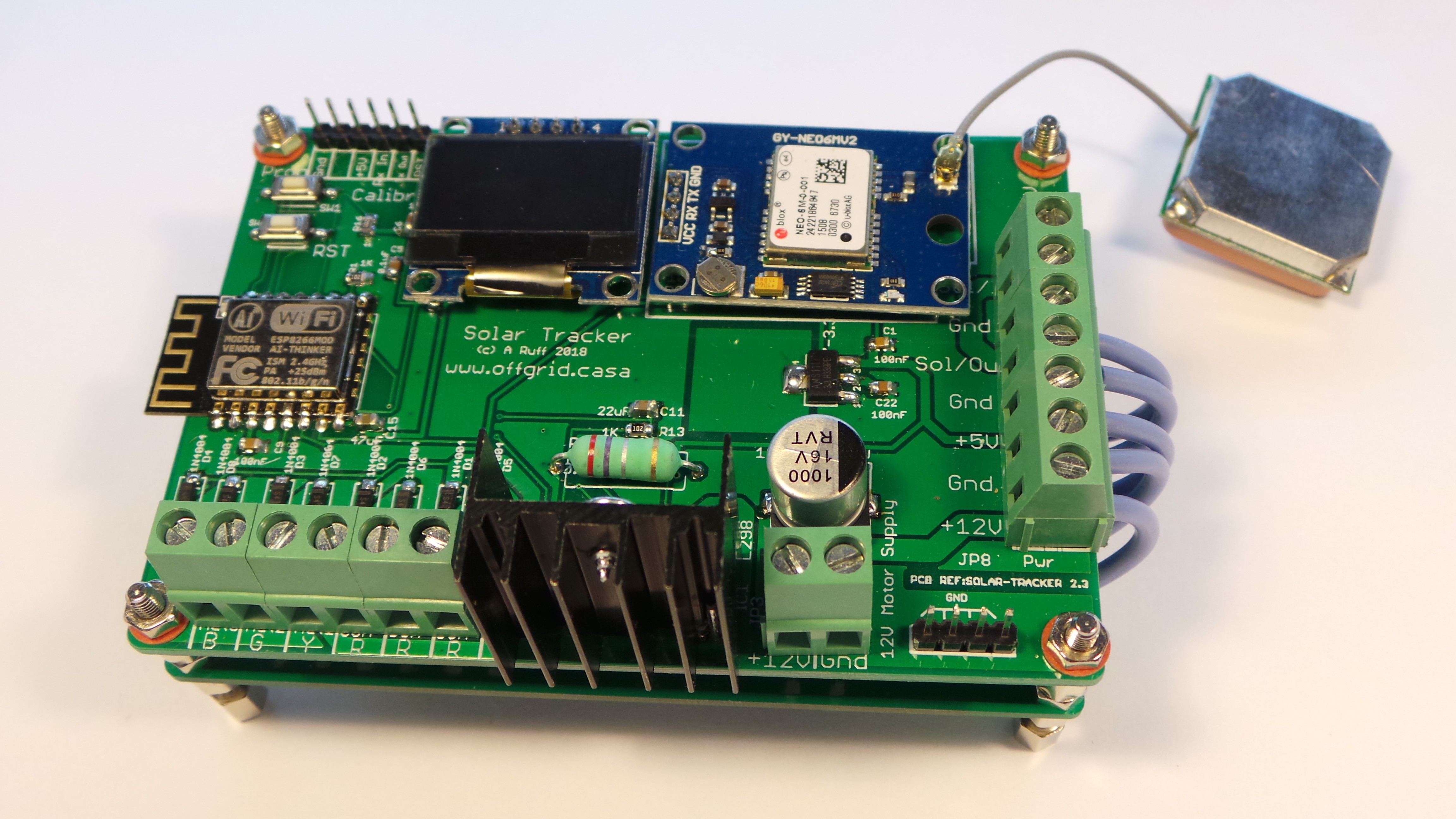
The finished prototype
My solar tracking metalwork is fairly simple. It uses eight cheap, stainless steel ball bearing hinges, some steel and two 4 inch (100mm) linear actuators. The initial prototype was in aluminium, but it's such a pain to weld, that I have moved to mild steel. You don't actually have to weld it together as you can just use bolts, but I would rather weld it all up then take to a powder coating company to have it all weather sealed. This costs around £10 ($14) per tracker. On each tracker I'm using 3 x 24V, 260W Candian-Solar panels in series to give me around 90 volts to the inverter which is the MPPSolar PIP4048 off-grid charger/inverter (http://www.offgrid.casa/solar-chargermains-inverter/).
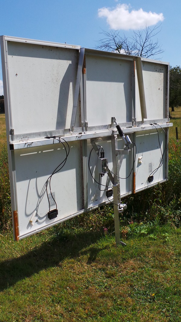
Here's the prototype unit with the tracking module bolted to the left hand support strut. There's only one panel in place as I was messing around with the easiest method of mounting when I took the picture. In a nutshell, I have made two tabs out of metal which are placed at the centre balance point of each panel and then they can be easily lifted into position and hooked over the elevation bar. Then, pop a single bolt in the top of the panel into the bracket that you can see behind the solar panel and it is secured nicely.
The First Panel Mounted onto the Tracking Unit
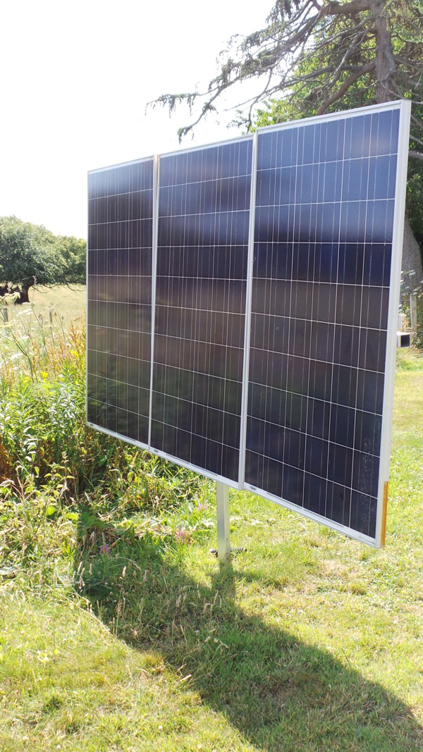
Three Panels Mounted
EASY CALIBRATION AND SETUP
This video shows the panel going through its' paces and demonstrates how easy it is to calibrate it. You need to be able to measure the sweep elevation angles - I printed out a simple protractor from the web and then measured the vertical angles that the panel can adjust between.
To measure the horizontal angles or azimuth angles that the panel can adjust between, I simply used the web setup page which allows you to set the panel to its' maximum and minimum positions and then I just sighted along the panel like a gun sight and then looked at Google Earth to get the actual bearings. You can, of course, use a compass, but don't forget to look up what the magnetic variation is for your location or you get it wrong. Remember the old pilots saying "West is best and East is least". In otherwords, if you have a magnetic variation of 5 degrees west, then add 5 degrees to you compass heading to get the true bearing. Similarly, if you have a variation of 5 degrees east, then just subtract 5 degrees from the compass bearing.
THE ELECTRONICS
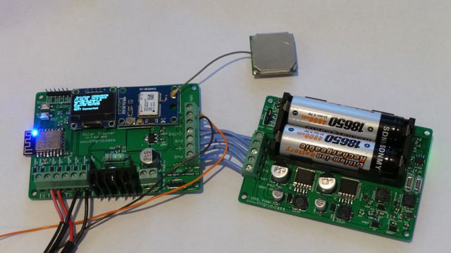
This pictures below show the two circuit boards that comprise the solar tracking module. The left hand one is the control electronics based on an ESP8266 wifi processor. There's a display for status information and to the right of that is a GPS receiver module - the square, silver bit attached by a grey wire is the receiver antenna.
The right hand circuit board is the power supply module. It takes the 30 or so volts from a 24 volt panel and converts it to 5V, 12V and also takes the 4.2V given by the Li-ion batteries and converts it up to 12V and 5V so that the electronics can carry on working in the dark. There's also a Li-ion battery charger which also temperature stabilises the batteries during the charging process to extend battery life.
Why does the unit need to carry on working in the dark? After all there's no sun! Well, firstly it means that the panels can stay pointed at the setting sun until true darkness, not just sunset, and can therefore gather up the very last of those lovely, power generating photons. They can then use battery power to rotate round to point at where the sun rises, thus really squeezing the most out of our stars radiation from dawn to dusk.
Also, if you hook the tracker up to a weather station and the wind gets up too high at night, you can send an MQTT command to the module to tell it to lay the panels flat so that they give the least wind resistance and therefore stand the lowest chance of being damaged in a storm. Of course, if you also have a wind generator, you'll be sucking up power like it's going out of fashion when the gales blow, so happy days.
POWER SUPPLY
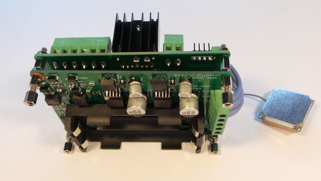
The tracking control electronics is on two PCBs. The first is a power supply which has a number of buck converters to take in the 24V-30V DC from one of the solar panels which is fed into and out of the housing for the circuitry. This means that there is no power supply or communications wiring - I use wifi to send status data to a remote server here in the UK. There is also an on-board Li-ion battery which drives the circuitry and the 12V motors when it gets dark via a buck boost circuit which is selectable for either 6V or 12V. The panels are connected in series to the inverter giving a total of around 90V, which also keeps the cables from needing to be too thick.
For longevity of the motors and gearing, I'm using 6V to drive the 12V linear actuator motors. Also, I'm using PWM (pulse width modulation) to slowly increase and decrease motor speed to reduce whiplash in the gears. However, there's a link to select 6V or 12V and if you want 24V , you can change one resistor.
TRACKING ELECTRONICS - The clever bit
The second PCB conatins the intelligence of the system. It's based around the Espressif ESP8266 wifi processor. There's a small OLED status display and a cheap GPS module (around £1.50 or $2). Other tracking systems that I've seen use optical tracking methods to keep the panels pointed at the sun. However, they can have issues on cloudy days when there is still some power available but no direct sunlight and need some sort of optical array. For the cost of a GPS module and some fancy footwork with the maths, I've made the tracker completely independent of optics. The satellites supply the time, date, latitude and logitude to my unit which then figures out where on the planet it is and uses the time and date to align the panels with the sun.
You log onto the wifi setup access point that is generated by the tracker and then open the setup webpage and input a few angles - i.e. how far your panel can track from left to right and up and down. You can also specify passwords and a remote MQTT server if you want monitoring data and remote control.
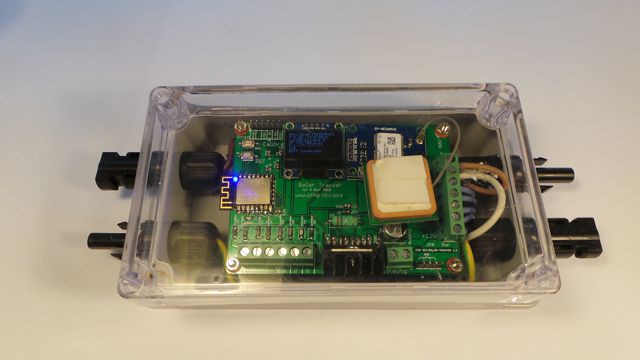
The images above below show the power supply and tracking module combined and in a weatherproof box with the solar input and output connections. You can simply plug the unit between the solar panels and the load and it will tap off a small amount of power to keep its' battery charged.
SAFETY
I have also designed a weather staion which monitors temperature, pressure, humidity, wind speed plus solar and battery power. This units also communicates via MQTT with the remote server, so if the wind speed gets too high and could potentially damage your panels, you can automatically set the panels to the horizontal so that the wind flows over them rather than catching them like a sail.
MONITORING
My pal Pete Scargill and I have spent a ridiculous amount of time developing some ESP8266 drop-in software known as esp-go, plus a setup script for a Raspberry Pi or simliar. This has become known as The Script and is now used by thousands of hobbyists and engineers around the world and is free for you to use. The Script configures your linux based computer and installs an MQTT server, database manager, Node-Red and a number of other useful programs.
Node-Red was written and is maintained by IBM and is an easy to use, graphical system to create control flows. So, in the example of the wind getting too high given above, you can send the wind speed readings to a simple node which if the wind speed goes above a pre-determined level it can then send the command to the solar tracker to lay the panels flat. It can also log data such as power, wind speed etc.
This is a screen shot from the MQTT message queue of my Raspberry Pi. This is the unit that will control all of the power systems in my house using Node Red.
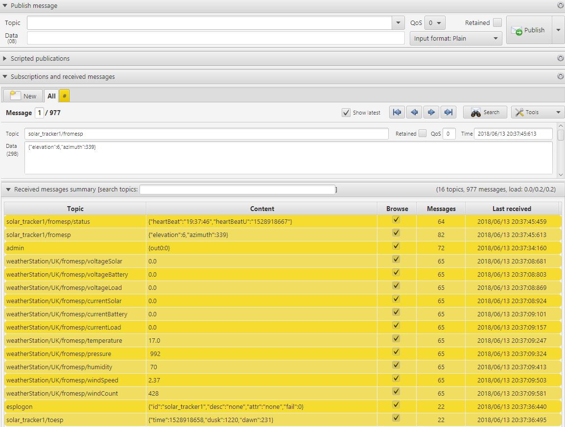
You can see the text messages that are being exchanged between the Raspberry Pi, the solar tracker and the weather station. The first message topic is "solar_tracker1/fromesp/status" and is simply a message that is sent every minute from the tracker to tell the Pi that it's working. The next message tells the Pi what elevation and azimuth angles the panels are set to. There are also a few error messages that can be sent such as if the panels stop moving.
The messages below are from the weather station on the roof, which isn't connected to a solar panel so it's not showing any power readings. However, it is showing weather information.
MAINS POWER
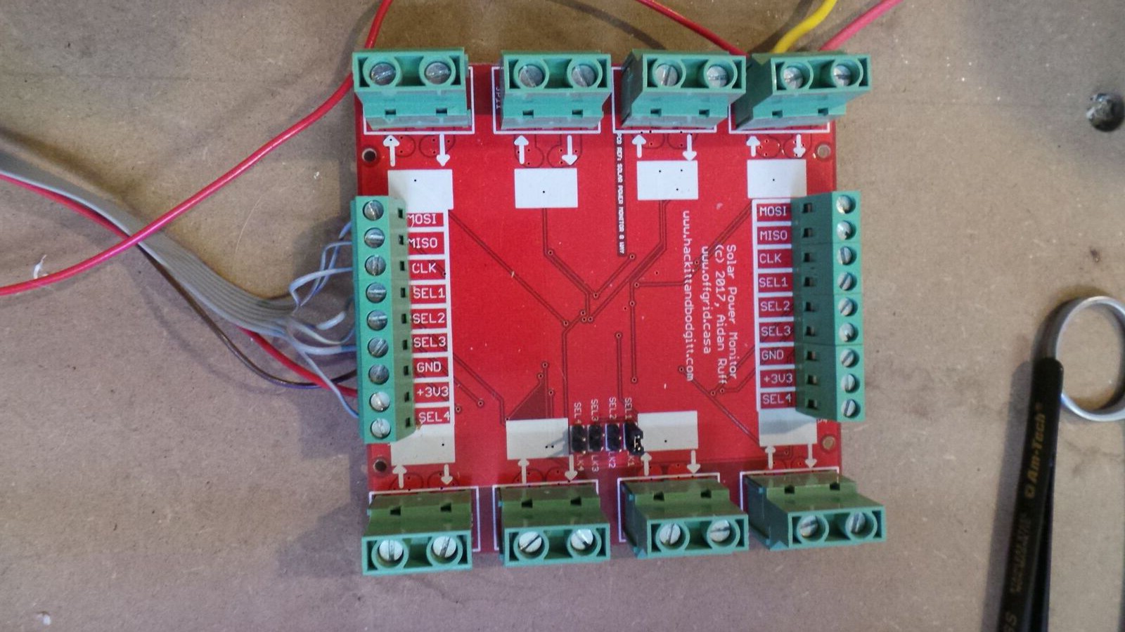
I have been a very busy little bee and have also designed a circuit that will monitor each group of solar panels. Imagine if like me, you have 20 sets of 3 panels and one of them develops a fault. How would you know until more became faulty and you started to lose power?
Each of these monitor boards will handle up to 8 sets of panels with up to 20 amps each and you can cascade up to 4 boards giving you a potential of 32 panel groups. In my case with 3 panels per group that would give you the abillity to monitor over 50KW of solar panels!
8-Way Solar Power Monitor
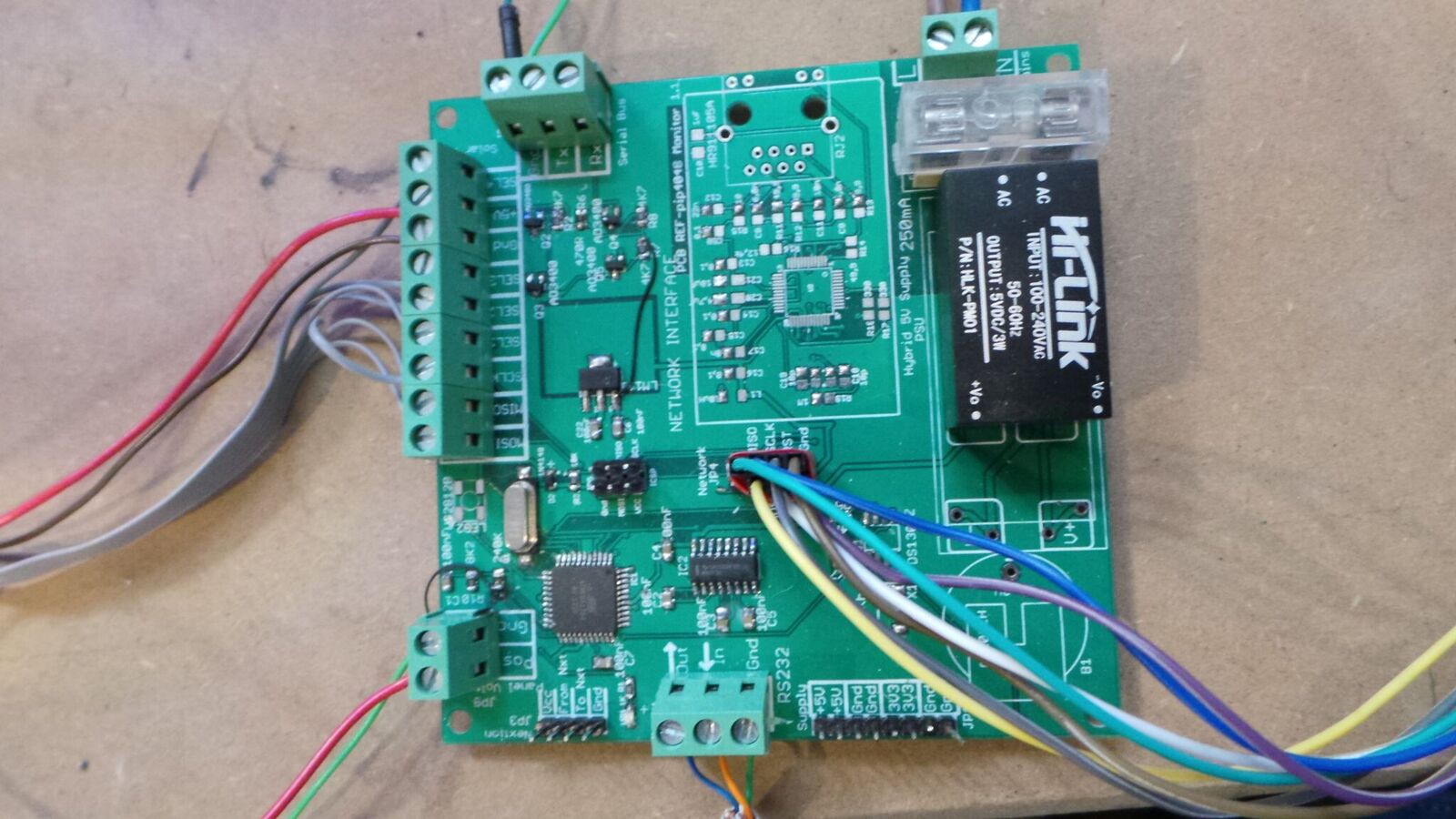
Here is the MPPSolar PIP4048 interface which also reads the power levels from the 8-way power monitor. It has an onboard network interface so that it can also communicate with your MQTT server and upload inverter and solar panel power readings to your mysql database so that you can keep an eye on what you're getting out of your system.
This information is really at the heart of power optimisation using my system as it will allow your Node Red/Raspberry Pi system to make intelligent decisions about what to do with your available solar and battery power to achieve the best results and not run out.
The current levels are read using an i2c interface and four select lines, giving you the ability to read 8 x 4 currents. You could easily read this with a Raspberry Pi using the on-board i2c interface and parallel outputs. However, I decided to design yet another circuit board, after all why do things the easy way?
PIP4048/Power Monitor
Logging Power and weather readings
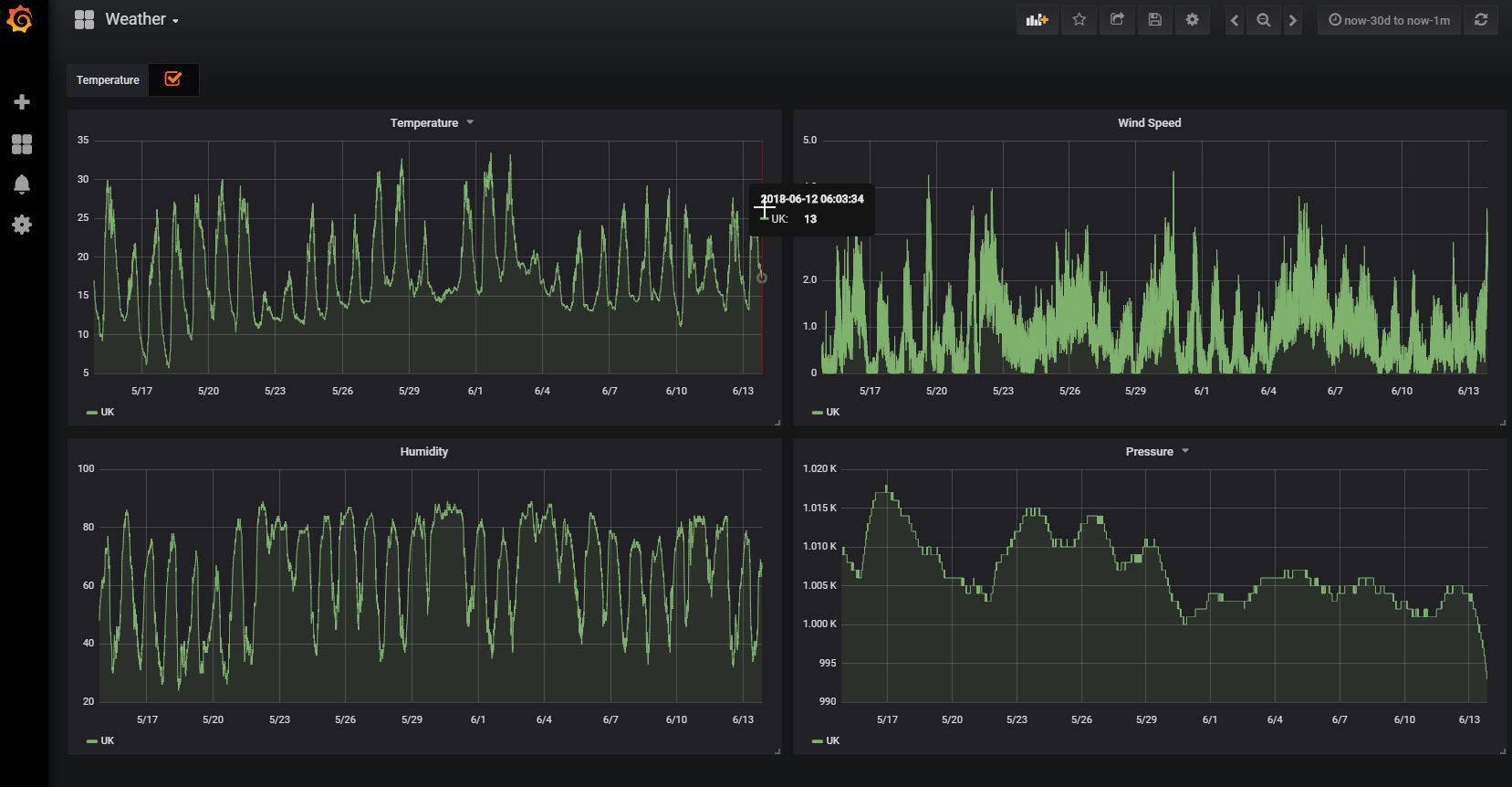
Using the Mysql database manager on the Raspberry Pi you can store the power and weather readings and use a tool like Grafana to create some very pretty graphs. Also, you'll then be able to see if any of the panels have malfunctioned or maybe just need the grass cutting in front of them.
Here's an example of the data that I've been storing from two weather stations, one here in the UK and the other one on our land in Spain.
CIRCUIT BOARDS FOR YOU TO MAKE
I have uploaded to the file section all of the PCB files, schematics and production files. If you want to make a set of PCBs, just take the two zip files and upload them to your favourite manufacturer. I've been successfully using jlcpcb.com for some time now and their service is fast and cheap. You can get 10 sets of both blank PCBs manufactured and delivered for around £25 ($30).
THE STEELWORK
If you're not confident in cutting up and either bolting steel together, I'm sure that you can find a local metalbasher who will do it for you. I've also uploaded PDFs which have all of the sizes and measurements needed. The hinges that I've used are from Ebay and are around £10 for 4 pairs. They are stainless steel, ball bearing, 4 inch (100mm) hinges.
THE LINEAR ACTUATORS
I've used 4 inch units because they are adequate and the cheapest. Make sure that you get IP65 versions though because they are going to be outside. I also bought from Aliexpress some pairs of motor bike suspension gaiters. These were about a dollar per pair. These slip over the linear acutator arms to protect them from dust and are secured at either end with a jubilee clip.
UPLOADING THE SOFTWARE
I've provided the ESP8266 Arduino based code for you to play with. If you're not confident or interested in using the Arduino version, I've also included the binary files so that you can use something like the NODEMCU flashing tool to simply upload the files to the tracking control board. Don't forget to hold down the programming button on the circuit board and then press and release the reset button before triggering the flashing process. as this puts the ESP8266 into programming mode.