The Problem
The Silva Nexus Classic instrument system on our sailboat consists of a server, three transflective LCD displays, and sensors (knotmeter, depthsounder, wind speed, wind angle, and GPS). The 20 year old system continues to work; however, the displays have lost their contrast and antireflection (AR) coatings making them nearly impossible to read. Futhermore, the Nexus system is closed source and I've always been frustrated that I can't have more control of the processing of the sensor data. So before I replace the whole system, I'd like to see if I can build my own instrument system using the existing sensors. The outputs of all of the sensors are 5V pulses with information coded into the pulse frequency and/or pulse width which are easy to read with a microcontroller. A harder task (for me) is finding and packaging a suitable data display. Our Nexus data displays are mounted above deck, on the mast under the boom. The new displays will go in the same place so they must meet the following requirements:
- The digits of the new display must be visible from about 15 feet away in the cockpit
- The display must be sunlight readable
- The display must be readable at high angles
- The display must be waterproof to something like IP67
- The display must have an update rate of less than 1 second
In this Hackaday project I'm only going to consider identifying a display solution. I'll pick up the other tasks of the larger project separately.
The Transflective LCD Display Solution
Most above deck marine instruments use transflective LCD displays. They rarely have touch screens because the extra layers of the touch screen increase glare from the display. To protect the LCD from water it is mounted inside of a waterproof enclosure behind a clear plastic or glass plate. The front of the LCD is bonded to the back/inside surface of the plate using a liquid optically clear adhesive (LOCA). The front/outside surface of the plate also has an antireflective coating to reduce glare. The number of choices of and interactions between the LCD, LOCA, plate, and AR coating are sufficiently intimidating that I'm choosing to consider an alternative solution first.
The E-Paper Display Solution
Requirements
E-paper displays are well known for their excellent readability under direct sunlight so I soon found Waveshare's 2.9 inch EPD offering. This display matches up well to my requirements:
- In landscape orientation with three digits in the full viewable area of the display the digits are larger than the top line of data in the Nexus display
- The sunlight readability of the EPD is at least as good as the transflective LCD
- The high angle readability of the EPD is superior to the transflective LCD
- The display is made of waterproof materials but may have to be packaged to prevent water from getting to its edges and to where the FPC ribbon cable leaves the package
- This EPD has a 0.3s partial update rate which can be applied to the individual changed digits
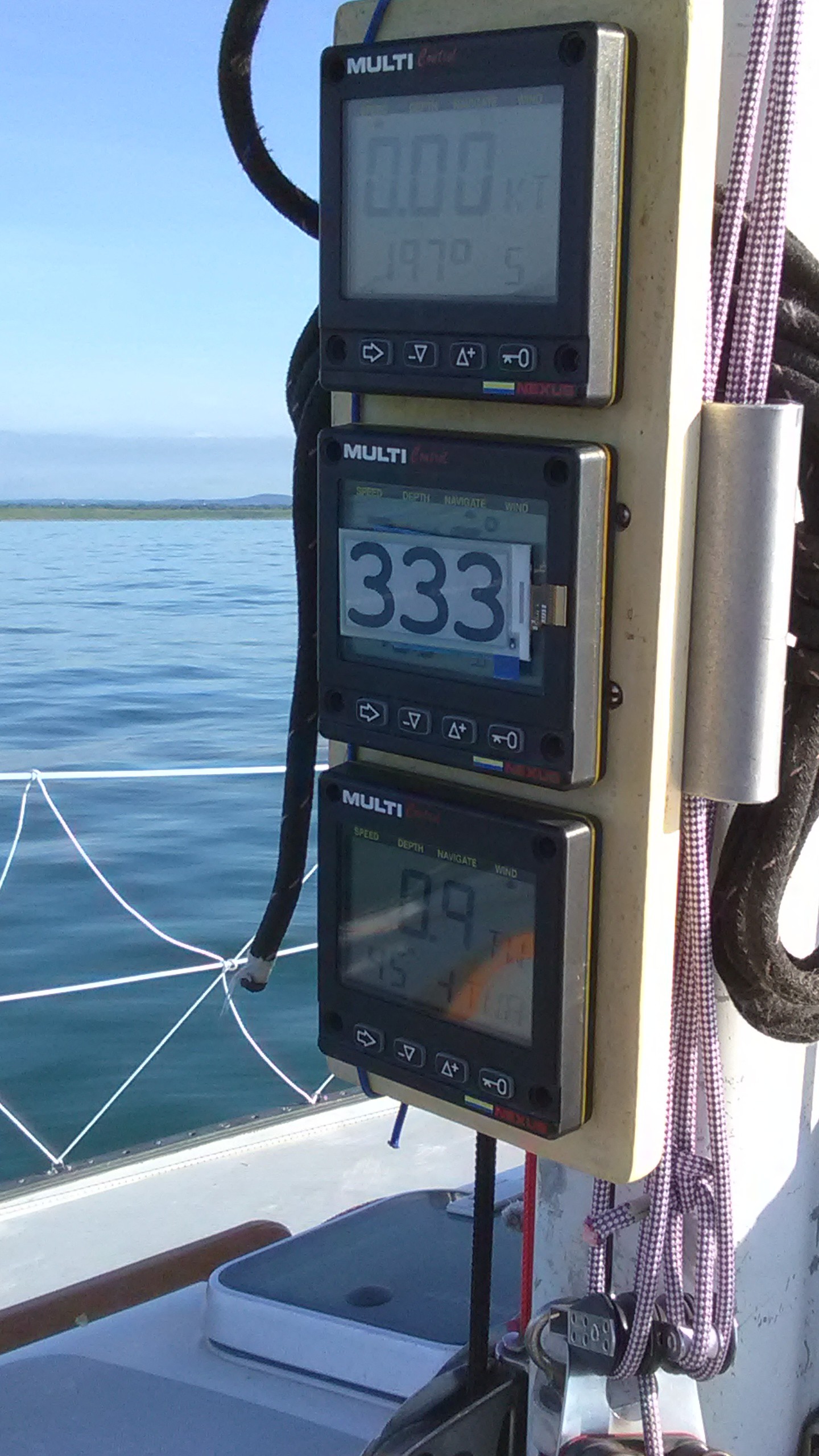
The picture below shows our Nexus displays with an EPD taped to the front of the middle display. The improvement of the EPD over the Nexus displays in terms of character size, contrast, and display glare is obvious.
E-paper Display Driver Software
I investigated three different Arduino libraries to drive the EPD:
I got the Arduino EPD demo software for all three libraries to run with a little effort; however, I ran into difficulties when I tried to use GxEPD and U8G2 with very large fonts and/or partial updates so I ended up back with epd2in9. GxEPD and U8G2 are still very impressive libraries with excellent support from Jean Mark and Oli, respectively, and I highly recommend them.
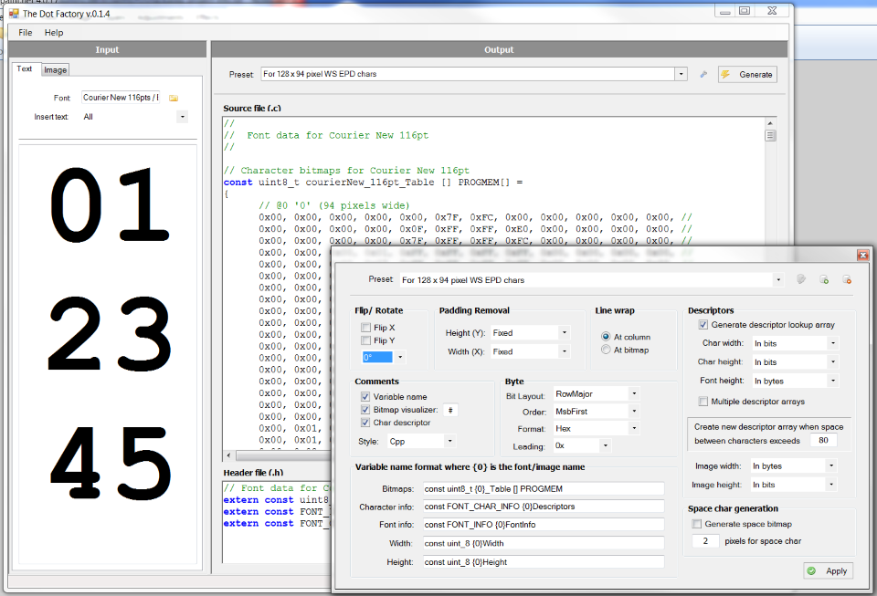
The epd2in9 library comes bundled with several font files of different character sizes but the largest font was 24 point so I had to create my own font file. I used Eran Duchan's excellent program TheDotFactory to create a font file for the characters 0-9. I chose a Courier New font because its characters are all of fixed width and 116 point font size produced characters that are 128 pixels tall by 94 pixels wide - perfect for displaying three characters on the 128 x 296 pixel display. The screen shot below shows how I configured TheDotFactory to create this font file. I still had to do some manual edits of the C file that the program produced but I just used the original epd2in9 font file format as a template.
The Waveshare library file epdpaint.cpp contains the functions that draw pixels, characters, and geometric figures on the display. Its DrawCharAt() function requires a complete set of ASCII characters in the font file so it wasn't compatible with my new font file containing only the characters 0-9. I added a new function DrawMyCharAt() to epdpaint.cpp to find the character data in the new font file.
Waveshare's 2.9 inch E-Paper Displays
The thumbnails in the picture gallery and the following picture show Waveshare's 2.9 inch EPD offerings and controller connectors. There are four relevant products:
- The raw EPD with a 24 conductor FPC ribbon cable
- The EPD module consisting of a raw EPD mounted on a driver board with a JST connector and 8 pin breadboard breakout
- The E-paper Driver Hat with a JST connector and 8 pin breadboard breakout
- The ESP8266-12E EPD driver board with an FPC ribbon cable socket
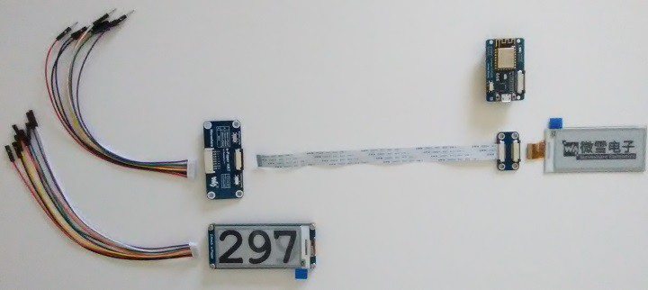
The EPD module and driver hat each have an 8 pin JST connector and breakout cable for use with a breadboard. The ESP8266 driver board has an on board FPC cable connector so the EPD can be connected directly to the driver board or to the FPC to FPC connector with the 12 inch extension cable and then to the driver board.
FYI: I ordered the EPDs, E-paper driver hat, and the 8266 driver board directly from Waveshare. Waveshare's web site is very well organized and the interface to enter my BOM with billing and shipping information was very easy to use. Waveshare shipped my order within one day and it took about two weeks to receive the order. All of the parts that I received were in good shape and worked as expected.
Wiring the EPD
The connections between the EPD and a microcontroller board are given in the following table. The EPD is a 3.3V device so a logic level converter is required when using the EPD module or EPD driver hat with the Uno and Mega2560. The Waveshare ESP8266's EPD connections are hard-wired to the FPC cable ZIF socket. All of these connections are assigned in my version of the epdif.h file.
| EPD | Uno | Mega2560 | ESP8266 |
| BUSY | 7 | 7 | GPIO16 |
| RST | 8 | 8 | GPIO5 |
| DC | 9 | 9 | GPIO4 |
| CS | 10 | 53 | GPIO15 |
| CLK | 13 | 52 | GPIO14 |
| DIN | 11 | 51 | GPIO13 |
| GND | GND | GND | GND |
| 3.3V | 3.3V | 3.3V | 3.3V |
Wiring the LSM303
If you intend to run the LSM303 tilt compensated compass demo: I am using Adafruit's LSM303 breakout board which is an I2C device. My demo sketch uses the following default I2C connections for the Uno and Mega2560 and custom connections for the ESP8266 driver. The ESP8266's custom pins GPIO0 and GPIO2 are required because its default I2C pins GPIO4 and GPIO5 are already used for the EPD.
| LSM303 | Uno | Mega2560 | ESP8266 |
| SDA | SDA (A4) | SDA (20) | GPIO0 |
| SCL | SCL (A5) | SCL (21) | GPIO2 |
| GND | GND | GND | GND |
| Vin | 3.3V or 5V | 3.3V or 5V | 3.3V |
The Clock and Compass Demo Sketch
The files required to run the clock and compass demo sketch are included in the attached .zip file. Extract these files to your preferred sketch location. You will also have to install Pololu's LSM303 library if you want to run the compass demo.
I had to modify Waveshare's original EPD library files to support the three different microcontrollers and the new font file so the .zip file contains my new versions of the Waveshare files. #include statements in the sketch were changed from < > to " " to reference these new files in the sketch folder instead of files that would otherwise be found in the \Arduino\libraries\ folder.
There are two #define compiler directives in the sketch that control which demo (clock or compass) is run and whether diagnostic print info gets sent to the serial monitor. Use the #define HasLSM303 directive to choose the demo and the #define DEBUG directive to turn serial debugging on and off.
When the sketch is compiled, the target microcontroller chosen in the Arduino IDE's Tools> Board list is used to determine the pin definitions as specified in epdif.h.
The 2D array intDigit[i][j] in the sketch is cryptic enough that it deserves some explanation. The first array index i can take on the values 0, 1, and 2 corresponding to the units, tens, and hundreds digits of the display, respectively. The second array index j keeps track of the recent history of the displayed values. The EPD controller has two internal frame buffers, one that is being displayed while the other is being updated. When the writing of new data to a frame buffer is complete, the controller toggles frame buffers. Because this sketch uses partial updates to update only the changed digits between readings, it is necessary to keep track of the data in both frame buffers and to keep a third buffer for writing the new data. j = 2, 1, and 0 correspond to the oldest, less old, and new frame buffer data, respectively. When the new values in j = 0 are ready, the data in j = 1 are written to j = 2 and then the j = 0 data are are written to j = 1. This is the algorithm that allows for 0.3 second single digit updates. The alternative would be to do full updates of each frame buffer which takes 2 seconds - too long compared to the less than 1 second update rate called out as one of the requirements.
The video below shows the sketch in action.
Potential Failure Modes of the EPD
In terms of some of the performance requirements the EPD looks promising as a large digit sunlight readable instrument display; however, there are still many potential failure modes that could kill it including:
- Will the display suffer thermal damage or UV damage when exposed to direct sunlight and heat?
- Will the contrast degrade too fast? (The displays are cheap enough that I'd be willing to replace them every year.)
- Will the EPD suffer from severe image burn in that limits its useful life?
- Will the number of updates to the display limit its useful life? (The rated life of the EPD is 1 million cycles but I don't know if this is based on real life test results or on guesses or extrapolations.)
- Will the EPD hold up when it's exposed to water and high humidity?
What's Next?
I've already written Arduino sketches to read the various instrument system sensors on the boat and process the data. The next step is to get some real on-the-boat experience with the EPDs to assess those failure modes mentioned above. I have hand drawn sketches (I have no CAD skills) of an enclosure for two EPDs and their drivers. I'd like to get this made this racing season so that I can have some results back this fall. If this enclosure is successful I will build a larger one for 6-8 displays.
My intent is to set the EPDs in rectangular recesses milled into the face of the enclosure to give them some mechanical protection. A narrow rectangular aperture will allow the EPD's FPC ribbon cable to pass through the front of the enclosure to the driver inside. I intend to bed the back of the EPD in a compatible adhesive (polyurethane?) and let excess adhesive squeeze out around the perimeter of the EPD to seal its edges and the FPC cable where it passes through aperture.
We do some racing at night and the EPDs require ambient light to be seen. I intend to put a socket for a wall-washing LED protruding from the enclosure face above each EPD to illuminate it from above.
How Can You Help?
Here are some questions that some of you out there might have answers for:
- Is the published 1 million cycle life of the display real?
- Is the EPD waterproof as is and if not, what areas/features of it need to be sealed?
- What adhesive is compatible with the EPD? The area where the FPC cable exits the EPD is already bedded in adhesive so Waveshare (or Good Display?) must know.
- What wall-washing lighting geometry will allow me to illuminate the EPD from above?
- If the units digit of the EPD wears out from suffering more updates than the tens and hundreds digits, can the EPDs be rotated 180 degrees at their half life to spread out the wear more evenly and extend the life of the display?