 Colin MacKenzie
Current limits is set on the A4988 stepper driver by a voltage on the Vref pin. The Pololu A4988 driver I had didnt have a dedicated pin to the VRef but it did have a via. This via is really connected to the center tap of the trim pot and we could place a resistor from this point to ground and based on ohms law it would pull Vref closer to ground depending on the value we use. If we instead use a tri-state GPIO pin of a arduino (for ex.) to provide our ground reference we can control our two current modes. Our GPIO pin is either in an input Hi-Z or output LOW state, we never use HIGH state. The Hi-Z state essentially disconnects our resistor. You should also disable pull-ups on the GPIO pin if you can but this will still work quiet well otherwise.
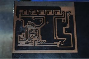
In my design I set my trim pot to give me 0.45v at Vref. Using the formula on the Pololu page, this provided up to 1.1A of current to the stepper motor. For my idle mode resistor I used a 500ohm, connecting it from the via as shown in the first picture to my esp8266 microcontroller. In my code I set the pin to LOW output and toggled the pin mode between input/output to enable high-power or idle current state. I also controlled the A4988 ENABLE pin so I really had 3 power modes (high, idle and off).
The 500ohm resistor when grounded with the GPIO pin resulted in a Vref of 0.088v, which reduced the motor current to only 220mA and yet it still had enough holding power (along with mechanical friction) that I couldn't move the drawer. Furthermore, the A4988 ran cool in this mode so I feel confident it can last the test of time.
See the attached spreadsheet to calculate the proper resistor for your project. Choose your desired nominal motor current in the left section. Then use either the middle section to test IDLE current based on resistors you have on hand, or use the right-most section to calculate a resistor value based on your desired IDLE current. You can edit any of the plain white columns and the line values will update.
WARNING Ensure you never output a HIGH level on the GPIO pin. You will pull Vref to VDD through the IDLE resistor and will likely set the A4988 to max current of 2A. You will likely send the A4988 quickly into thermal shutdown. This is why we use the Hi-Z state by setting the pin to an INPUT as this electrically disconnects the IDLE resistor.
 utsourceproduct
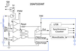
 Adrian Freed
 UTSOURCE
Hi Colin and thanks for sharing that tip.
However if you're still working on that drawer and it's power consumption I'd like to suggest a possibly easier way to do it with the same hardware. I've been studying deeply the inner workings of these cheap stepper modules lately and the chip at the heart of them A4988.
Turns out that the current limiting capability of the module is done with hysteresis current control (also known as current chopper) , kind of like bang-bang control, where it lets the current rise until the set value and then shuts down the power for a couple microseconds then repeat, which effectively keeps the current at all times in a range below the set value. This happens in the background (at 10+KHz I believe) , regardless of the enable, step or direction pins status.
Another important thing is that the enable pin defines whether power is delivered to the mosfets or not, but it doesn't cut power to the chip therefore it doesn't reset it or anything, it just blanks the output stage.
Now comes the trick, assume you set the max current to 1 amp with the tiny potentiometer. Since the current flowing through the windings of the motor is (somewhat) constant in time, you can go ahead and pwm that enable pin, and as a result, you will be injecting the corresponding fraction of the 1 amps you have as a limit. That's more or less how the internal sine wave generator does the microstepping (not on the actual enable pin but same principle internally).
Effectively both your method and this one should have similar outcomes, but this one might be easier to implement as it doesn't require ninja soldering which I wish I was good at.
I hope this somehow helps!