 Luke
LukeSome time has gone by since my last log update.
ELECTRONICS
During that period the PCBs and parts arrived and I assembled one timer :)
The assembly process went smooth. The smallest parts are LED driver and battery charger (0.5mm pitch QFNs) and I used microscope when soldering them down. Rest of the components went easy (passives are in 0805). On hiccup I encountered was swaped (misplaced) labels of two resistors (R21 and R22), but I spotted it pretty quickly, since voltage converter was not working properly with these resistors swapped (they provide feedback voltage to the converter).


FIRMWARE
After timer was assembled, I moved on to initial firmware development. I tested two toolchains/compilers: SDCC and ST Visual Develop (with Cosmic toolchain).
As far as I can see, there's no straightforward way to use debugger with SDCC toolchain (I may be mistaken). STVD+Cosmic has debugging capability built-in the IDE, which was a big plus for me. Also libraries provided by ST (called SPL - Standard Peripheral Library) were better suited for Cosmic compiler.
I created 'blinky' projects for both SDCC and STVD and after that decided, that I'll use STVD+Cosmic combo.
So far I've implemented 'millis' timer (using Timer2) and LED driver (using SPI and DMA).
Code is available on GitHub.
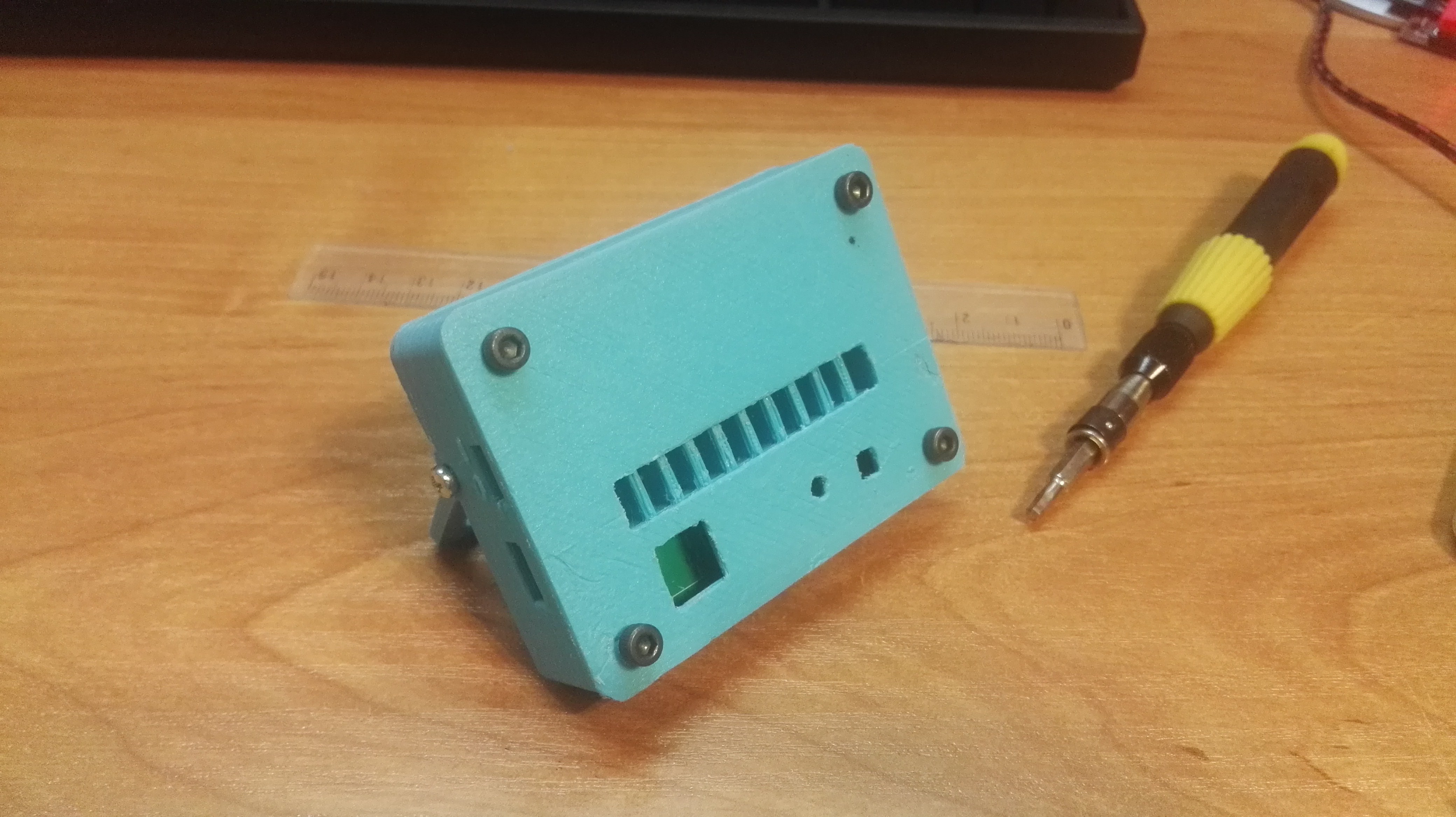
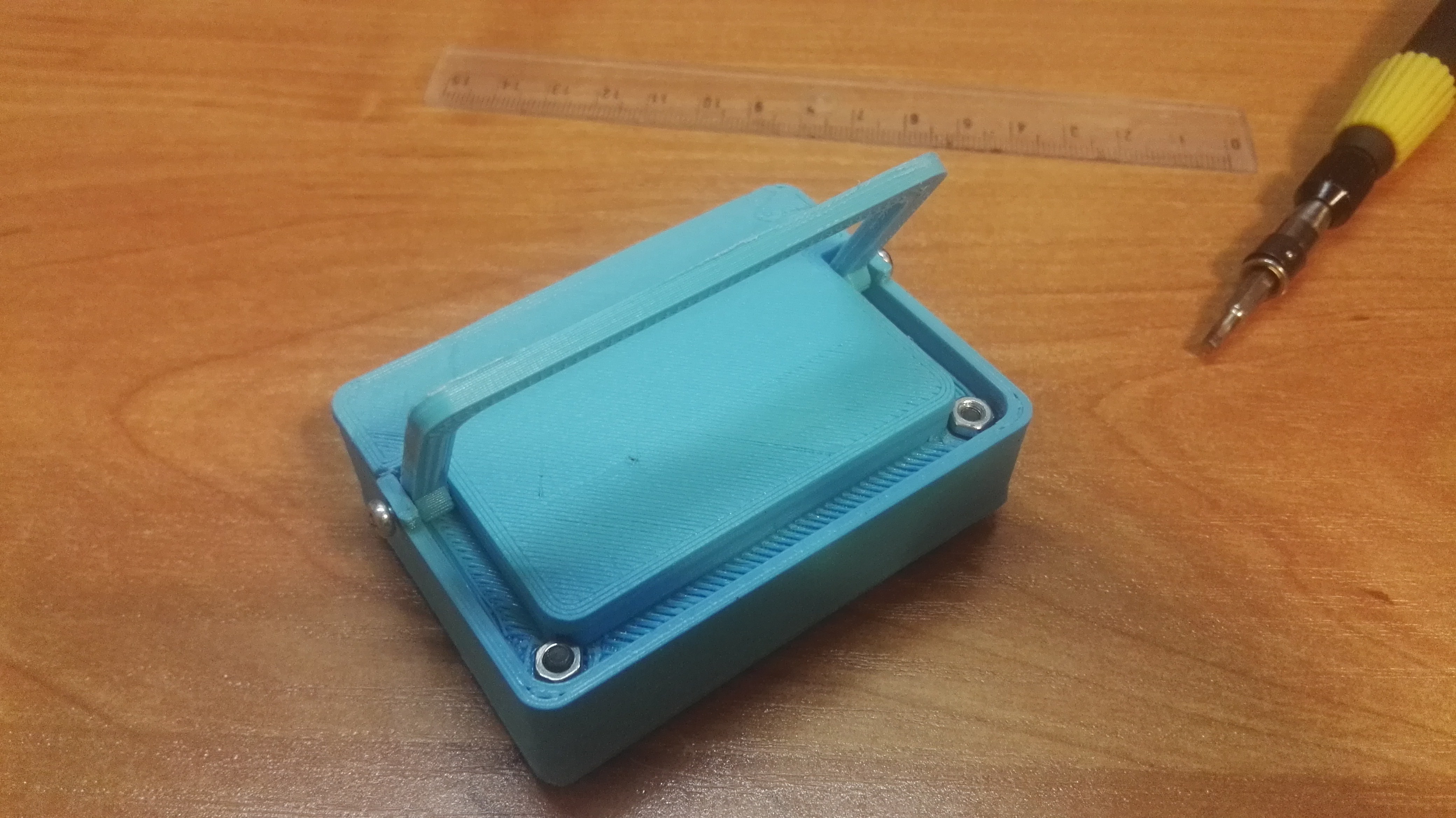
MECHANICAL
Case elements were 3D printed to see how they fit. The result is not bad, but I had to make a few changes in the design. Next week I'll probably print improved design.
Discussions
Become a Hackaday.io Member
Create an account to leave a comment. Already have an account? Log In.